
Peculiar smell removing equipment

A technology for odor removal and equipment, which is applied in the separation of dispersed particles, chemical instruments and methods, and filtration of dispersed particles, and can solve problems such as the weakening of the filtering effect of the filter cotton layer.

Inactive Publication Date: 2020-10-02
福州库菲思信息技术有限公司
View PDF6 Cites 0 Cited by
  • Summary
  • Abstract
  • Description
  • Claims
  • Application Information

AI Technical Summary

Problems solved by technology

[0003] Based on the above-mentioned discovery by the inventors, the existing methods mainly have the following disadvantages, for example: because the smelly air will contain dust floating in the air, when the peculiar smell removal device is started, the dust will be sucked into the device for filtration and purification, The dust volume is small and easy to pass through the flow holes and be directly intercepted and adsorbed by the filter cotton layer. With the gradual increase of the use time, a layer of dust will be attached to the surface of the filter cotton layer, which will weaken the filtering effect of the filter cotton layer.

Method used


Image

  • Peculiar smell removing equipment
  • Peculiar smell removing equipment
  • Peculiar smell removing equipment

Examples

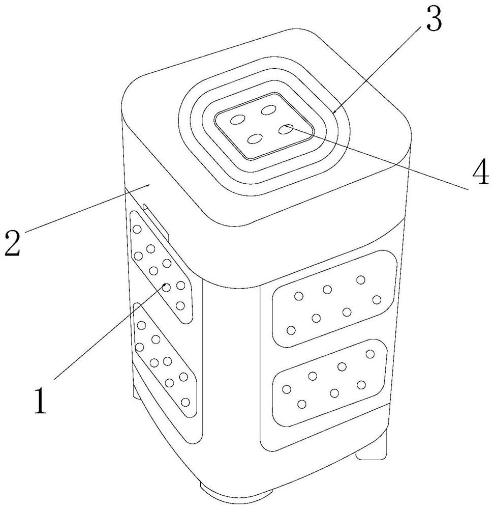
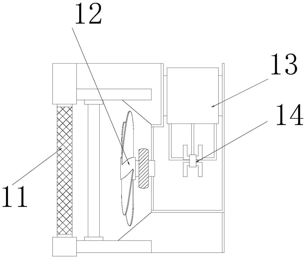

Embodiment 1

[0025] as attached figure 1 To attach Figure 4 Shown:

[0026] The present invention provides a kind of peculiar smell removing equipment, its structure comprises filter system 1, equipment box 2, vent hole 3, central control panel 4, and described filter system 1 is embedded and installed on the outer end surface of equipment box 2, and described equipment box 2 The air outlet 3 is inlaid and engaged with the upper end surface of the air outlet 3, and the air outlet 3 is embedded and installed directly above the filter system 1, and the central control panel 4 is located at the center of the upper end surface of the air outlet 3; the filter system 1 includes Filter screen plate 11, impeller 12, filter core 13, vibration mechanism 14, the filter screen plate 11 is inlaid and installed on the left side of the impeller 12, the impeller 12 is movably mounted on the inner end surface of the filter system 1, the filter core 13 is embedded and installed on the inner end surface o...

Embodiment 2

[0032] as attached Figure 5 To attach Figure 7 As shown: the vibration mechanism 14 includes a vibrating rod 141, a vibrating ring 142, a rotating blade 143, and a clamping ring 144. The vibrating rod 141 is inlaid and installed on the outer end face of the vibrating ring 142, and the outer end face of the vibrating ring 142 is evenly inlaid The rotating blade 143 is engaged and connected, and the rotating blade 143 is symmetrically installed on the left and right sides of the outer end surface of the vibrating ring 142. The clamping ring 144 is installed on the upper end surface of the vibrating rod 141 by welding, and the vibrating rod 141 is provided with Four of them are evenly engaged and connected to the filter element 13 in a ring shape, which can effectively transmit the vibration brought by the vibration ring 142 .

[0033] Wherein, the vibrating ring 142 includes a toggle block 421, a fixed ring 422, a vibrating block 423, a connecting rod 424, and a conductive bl...


PUM


Abstract

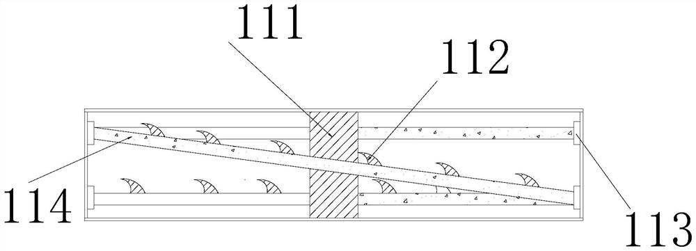
The invention discloses peculiar smell removing equipment. The equipment structurally comprises a filtering system, an equipment box, an air outlet hole and a central control board, wherein the filtering system is embedded and fixedly mounted on the outer side end surface of the equipment box; the air outlet is embedded and clamped in the upper end surface of the equipment box; the air outlet holeis fixedly embedded right above the filtering system; the center control plate is located in the center of the upper end face of the air outlet. Dust is filtered and precipitated to the surface of aninclined filter screen by utilizing a second filter screen plate; air flows downwards through the inclined filter screen and directly flows to a filter element through the corner design of the secondfilter screen plate, dust is preferentially filtered through the inclined design of the filter screen plate, and the situation that when peculiar smell air is purified, dust driven by air is attachedto the surface of the filter element, and therefore the filtering effect of the filter element is reduced can be effectively avoided.

Description

technical field [0001] The invention belongs to the field of air deodorization equipment, and more specifically relates to an odor removal equipment. Background technique [0002] Odor removal equipment is a device with the same working principle as air purification equipment. Usually, after inhaling odorous air through the flow hole, the cotton layer in the filter device absorbs the odor in the flowing air, and then pushes it out of the equipment. , to complete the process of air filtration. [0003] Based on the above-mentioned discovery by the inventors, the existing methods mainly have the following disadvantages, for example: because the smelly air will contain dust floating in the air, when the peculiar smell removal device is started, the dust will be sucked into the device for filtration and purification, The dust volume is small and easy to pass through the flow holes and be directly intercepted and adsorbed by the filter cotton layer. With the gradual increase of ...

Claims


Application Information

Patent Timeline
Patent Type & Authority Applications(China)
IPC IPC(8): B01D46/24B01D46/10B01D46/00
CPCB01D46/10B01D46/24B01D46/76
Inventor 沈义勇
Owner 福州库菲思信息技术有限公司
Learn More