Multifunctional cleaning device and cleaning machine

A cleaning device and multi-functional technology, applied in cleaning devices, cleaning machinery, robot cleaning machines, etc., can solve the problems of poor cleaning effect, dirt residue, simple mopping mechanism, etc., to save labor and avoid secondary pollution. , good cleaning effect

Pending Publication Date: 2020-10-02
SUZHOU TENGPU ELECTRICAL TECH CO LTD
View PDF0 Cites 3 Cited by
  • Summary
  • Abstract
  • Description
  • Claims
  • Application Information

AI Technical Summary

Problems solved by technology

The sweeping machine walks on the ground and drives the mopping cloth fixed at the bottom of the sweeping machine to realize the mopping function. Its function is not to actively wipe the floor, but to passively mop the floor. The mopping effect is not good, and the mopping cloth is easy to get dirty. , Easy to get muddy, can't be cleaned automatically, and has to be cleaned manually after being dirty, which does not save manpower. The main reason is that the mopping mechanism is too simple. The mopping cloth is fixed at the bottom of the machine, passively in contact with the ground, and is It is stuck on the bottom of the machine, and the dirt cannot be cleaned at any time. During use, the mopping cloth has to be dismantled and cleaned many times manually. Dirt is likely to remain on the ground when the mopping machine is turning, reversing, etc.
[0003] In order to solve the above problems, a roller brush type floor mopping machine has appeared on the market. Although some of the above problems have been solved, the cleaning of the roller brush cannot be guaranteed during the cleaning process, and the cleaning effect is not good.

Method used


Image

  • Multifunctional cleaning device and cleaning machine
  • Multifunctional cleaning device and cleaning machine
  • Multifunctional cleaning device and cleaning machine

Examples


Embodiment Construction

[0020] The present invention will be further described below in conjunction with the accompanying drawings and specific embodiments, so that those skilled in the art can better understand the present invention and implement it, but the examples given are not intended to limit the present invention.

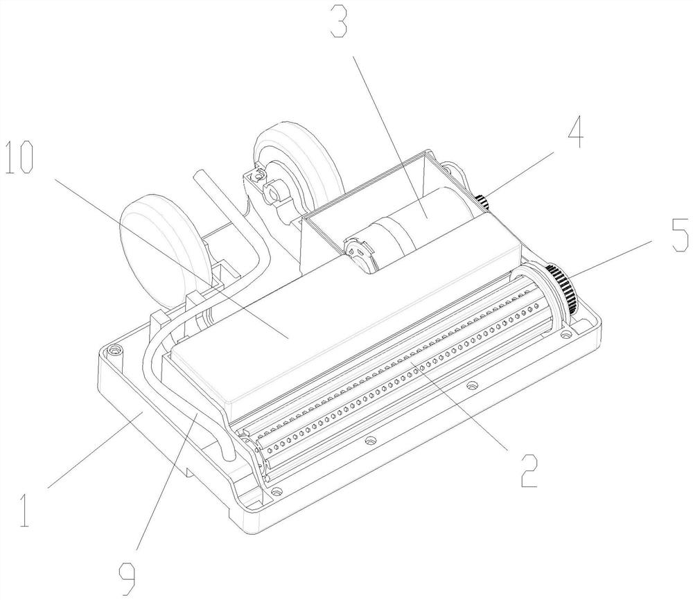
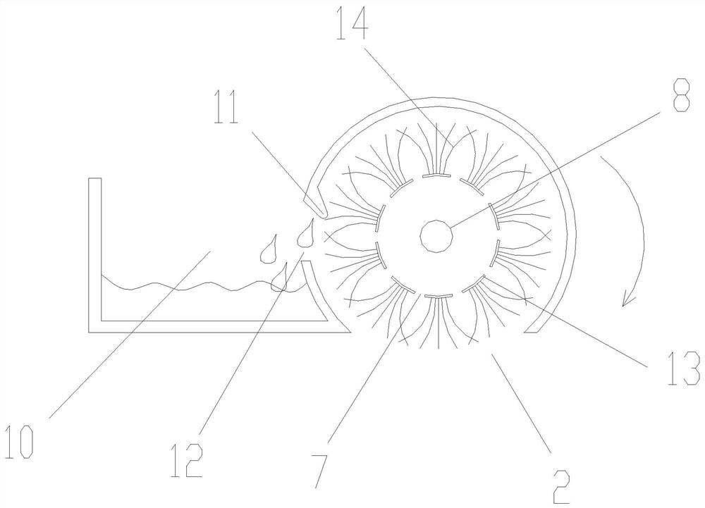
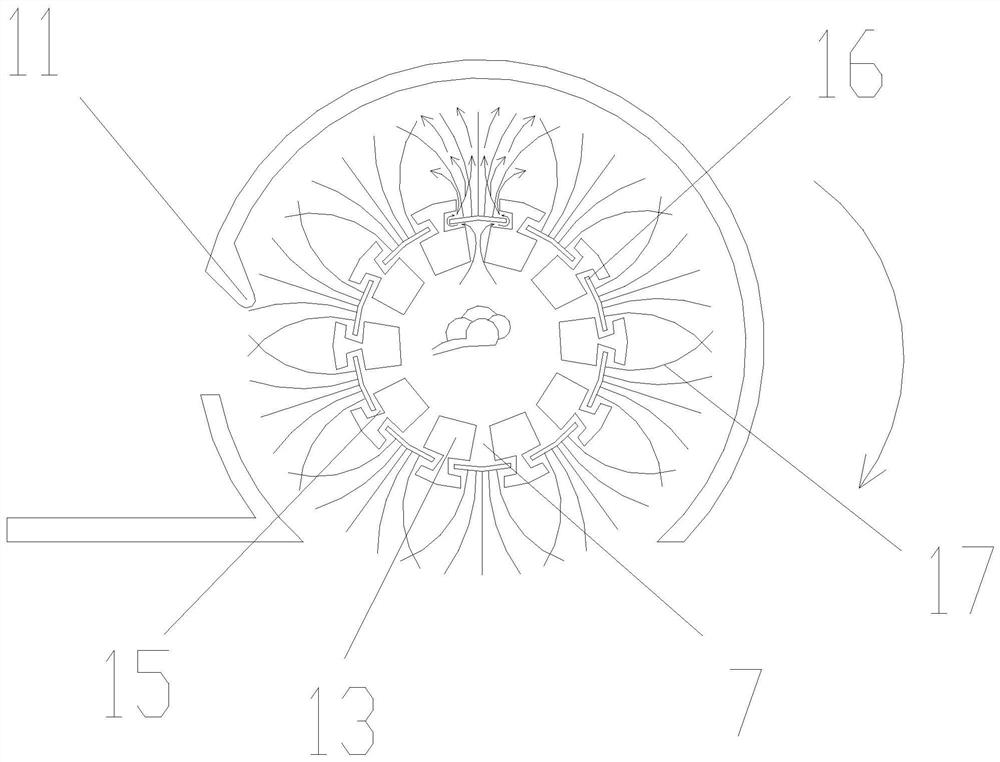
[0021] refer to figure 1 and figure 2 Shown is a schematic diagram of an embodiment of the multifunctional cleaning device of the present invention. The cleaning device of the present invention comprises a casing 1, an opening is provided at the bottom of the casing 1, a cleaning roller brush 2 is rotatably connected to the opening of the casing 1, and a motor 3 is arranged on the radial side of the cleaning roller brush 2, and the The motor 3 drives the cleaning roller brush 2 to rotate. The cleaning roller brush 2 is driven by the motor 3 to rotate at high speed. During the high-speed rotation, the cleaning roller brush 2 contacts the ground and rubs the ground at high speed ...


PUM


Abstract

The invention discloses a multifunctional cleaning device and a cleaning machine. The multifunctional cleaning device includes a shell, and an opening is formed in the bottom of the shell; a cleaningrolling brush is rotationally connected to the opening of the shell; a plurality of through holes are formed in the circumferential direction of the inner wall of the cleaning rolling brush; a spray pipe is arranged in the cleaning rolling brush; a connecting pipe is communicated with a purified water tank and the spray pipe; a cleaning agent flows into the cleaning rolling brush through the spraypipe and flows out of through holes in the circumferential direction of the cleaning rolling brush. A sewage tank and a motor are arranged on the radial side edge of the cleaning rolling brush, a water scraping plate abutting against the cleaning rolling brush is connected to the top of the sewage tank, a water collecting opening is formed in the position, corresponding to the water scraping plate, of the sewage tank, and the motor drives the cleaning rolling brush to rotate. The multifunctional cleaning device and the cleaning machine can achieve high-speed cleaning, saves labor in use, is good in cleaning effect, can achieve self-cleaning in the working process, and avoids secondary pollution caused by the fact that a cleaning machine moves back and forth to carry dirt.

Description

technical field [0001] The invention relates to the technical field of cleaning equipment, in particular to a multifunctional cleaning device and a cleaning machine. Background technique [0002] The mopping machine (mopping machine) for indoor household is based on the sweeping machine, which is a small vacuum cleaner (with smart walking function). ground function. The sweeping machine walks on the ground and drives the mopping cloth fixed at the bottom of the sweeping machine to realize the mopping function. Its function is not to actively wipe the floor, but to passively mop the floor. The mopping effect is not good, and the mopping cloth is easy to get dirty. , Easy to get muddy, can't be cleaned automatically, and has to be cleaned manually after being dirty, which does not save manpower. The main reason is that the mopping mechanism is too simple. The mopping cloth is fixed at the bottom of the machine, passively in contact with the ground, and is It is stuck to the ...

Claims


Application Information

Patent Timeline
Patent Type & Authority Applications(China)
IPC IPC(8): A47L11/292A47L11/40
CPCA47L11/292A47L11/40A47L11/4005A47L11/4041A47L11/4088A47L2201/00
Inventor 吕知轩
Owner SUZHOU TENGPU ELECTRICAL TECH CO LTD
Why Eureka
Try Eureka