Permanent magnet motor assembling jig and method thereof

A permanent magnet motor and assembly jig technology, applied in the direction of centering/balancing the rotor, etc., can solve the problems of assembly process obstruction and inability to complete

Inactive Publication Date: 2020-09-29
TECO ELECTRIC AND MACHINERY
View PDF3 Cites 0 Cited by
  • Summary
  • Abstract
  • Description
  • Claims
  • Application Information

AI Technical Summary

Problems solved by technology

[0010] In view of the fact that in the process of assembling the permanent magnet motor in the prior art, the stator structure and the rotor structure will be connected due to the mutual attraction of the magnetic force, which will hinder the assembly process, fail to complete and various problems derived therefrom

Method used


Image

  • Permanent magnet motor assembling jig and method thereof
  • Permanent magnet motor assembling jig and method thereof
  • Permanent magnet motor assembling jig and method thereof

Examples


Embodiment Construction

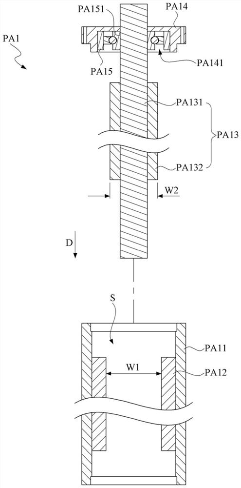
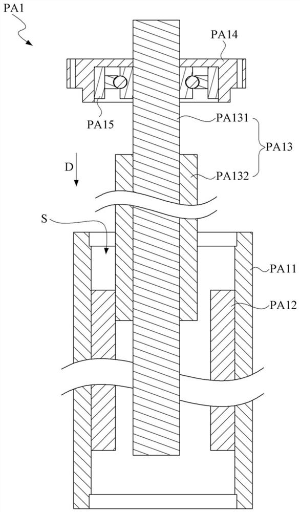
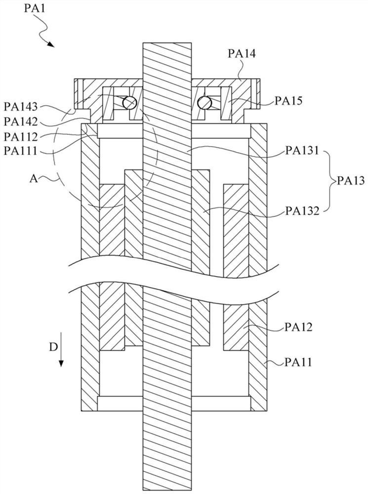
[0095] see Figure 5 to Figure 7 ,in, Figure 5 A perspective view showing the permanent magnet motor assembly jig provided by the preferred embodiment of the present invention; Figure 6 A three-dimensional combined view showing the guide tube and the fixed platform of the permanent magnet motor assembly jig provided by the preferred embodiment of the present invention; and, Figure 7 show Figure 6 The A─A sectional view. As shown in the figure, a permanent magnet motor assembly jig 1 is used to assemble a permanent magnet motor 2 (marked on Figure 12 ), including a fixed platform 11 , a guide tube 12 and a guide shaft 13 .

[0096] The fixing platform 11 includes a carrying component 111 and a fixing component 112 , and defines a through hole H. As shown in FIG. The carrying component 111 and the fixing component 112 include a carrying plate 1111 and a supporting member 1112 . The supporting plate 1111 is provided with the aforementioned through hole H and has a supp...


PUM


Abstract

The invention provides a permanent magnet motor assembling jig and a method thereof. The permanent magnet motor assembling jig is used for assembling a permanent magnet motor, and the permanent magnetmotor assembling jig comprises a fixing platform, a guide pipe and a guide shaft. The fixing platform is provided with a through hole and used for bearing and fixing a first assembling part of the permanent magnet motor. The guide pipe is aligned to the through hole to be fixed on the fixed platform, and is provided with a guide channel extending along an assembling direction. . The guide shaft is used for sequentially penetrating through the first assembly part and the guide channel along the assembly direction after being assembled on a rotor shaft in a second assembly part of the permanentmagnet motor, so that a second bracket is propped against the first assembly part, and the permanent magnet motor is assembled after the second assembly part and the first assembly part are fixedly connected.

Description

technical field [0001] The invention relates to an assembling fixture and an assembling method, in particular to a permanent magnet motor assembling fixture and a method thereof. Background technique [0002] A motor is a device that converts electrical energy into mechanical energy. It is indispensable in daily life and brings people a very convenient life. Among them, motors can be divided into induction motors, synchronous motors and permanent magnet motors. [0003] The permanent magnet motor uses permanent magnets to generate the magnetic field of the motor. It does not require induction coils or induced currents. Its advantages lie in high efficiency, high power factor, large starting torque, low temperature rise and simple structure. With the advent of high-performance permanent magnet materials and the rapid development of control technology, the application of permanent magnet motors is becoming more and more extensive. [0004] Please also refer to Figure 1 to Fi...

Claims


Application Information

Patent Timeline
IPC IPC(8): H02K15/16
CPCH02K15/16
Inventor 洪联馨何明特罗政伟
Owner TECO ELECTRIC AND MACHINERY
Why Eureka
Try Eureka