
Constant-temperature, constant-humidity and dustproof electrical cabinet

A technology of constant temperature and humidity, electrical cabinets, applied in the field of electrical cabinets, can solve the problems of easy damage to electronic components, flooding of electrical cabinets, lack of dustproof structures, etc., to improve heat dissipation and cooling efficiency, facilitate dustproof and rainproof, Ease of temperature control

Inactive Publication Date: 2020-09-29
刘泽楷
View PDF7 Cites 1 Cited by
  • Summary
  • Abstract
  • Description
  • Claims
  • Application Information

AI Technical Summary

Problems solved by technology

[0002] The electrical cabinet is made of steel and is used to protect the normal operation of the components. However, the electrical cabinets used in the prior art are usually not convenient for rapid and comprehensive cooling, and the area cooled by the cooling equipment is often subject to large volume. The blocking of components reduces the overall cooling efficiency of the components inside the cabinet, which in turn makes the electronic components inside the electrical cabinet vulnerable to damage. At the same time, the electrical cabinets used in the prior art usually lack a dust-proof structure that is difficult to quickly replace and install. When replacing the dust-proof structure, it is necessary to open the cabinet door and use structural auxiliary tools to replace it, which makes the replacement efficiency of the dust-proof structure slower. In addition, the electrical cabinet in the prior art lacks a telescopic structure, and the height of the electrical cabinet cannot be adjusted. That is, it is easy to make the electrical cabinet installed in the lower position affected by the flood, because the treatment needs to be improved

Method used


Image

  • Constant-temperature, constant-humidity and dustproof electrical cabinet
  • Constant-temperature, constant-humidity and dustproof electrical cabinet
  • Constant-temperature, constant-humidity and dustproof electrical cabinet

Examples


Embodiment Construction

[0024] The present invention will be further described below in conjunction with the accompanying drawings and specific embodiments.

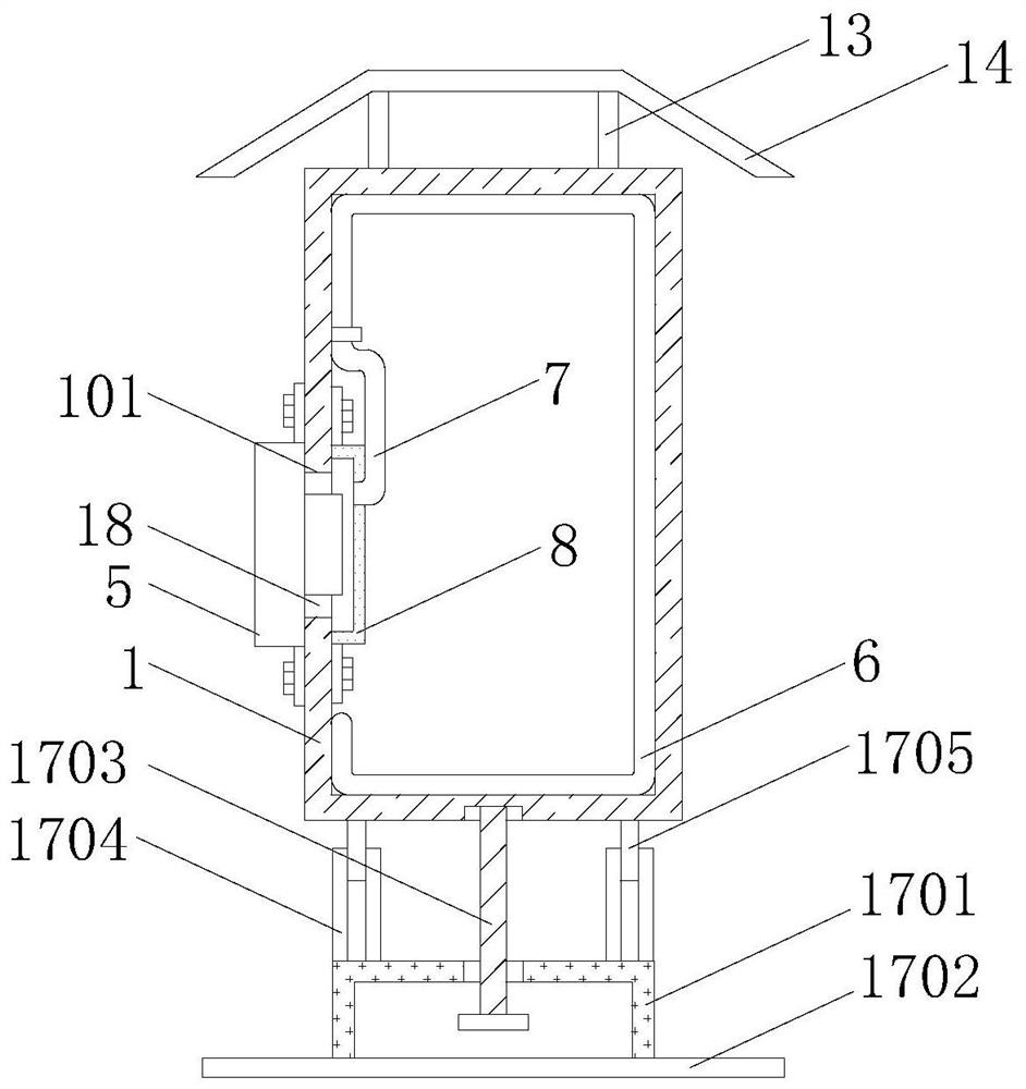
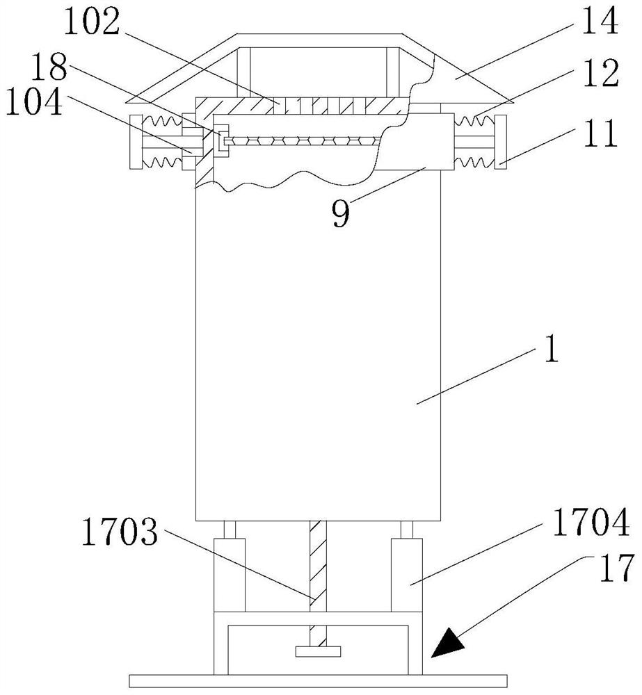
[0025] refer to Figure 1-6 It can be seen that a constant temperature, constant humidity and dustproof electrical cabinet of the present invention includes a cabinet body 1, and the inner wall of the cabinet body 1 is respectively fixed with a temperature and humidity sensor 2, a constant temperature and humidity controller 3 and a closing and opening controller 4 through screws. The cabinet body 1 is provided with a cavity 101, and the cabinet body 1 is fixed with a refrigerator body 5 through the cooperation of the cavity 101 and screws. The four inner walls of the body 1 are jointly welded with a transmission pipe 6, and the open end of the transmission pipe 6 is equipped with a hose 7 through a quick connector, and a transparent plastic cover 8 is glued to the outer end of the hose 7, and the transparent The plastic cover 8 is fixed on th...


PUM


Abstract

The invention relates to the technical field of electrical cabinets and particularly relates to a constant-temperature, constant-humidity and dustproof electrical cabinet. The cabinet comprises a cabinet body, wherein a temperature and humidity sensor, a constant temperature and humidity controller and a closing and opening controller are respectively fixed on an inner wall of the cabinet body through screws, a cavity is formed in the cabinet body, a refrigerator body is fixed to the cabinet body through cooperation of the cavity and screws, the cold air blowing-out position of the refrigerator body faces the interior of the cabinet body, transmission pipelines are welded to upper, lower, left and right inner walls of the cabinet body, and the temperature and humidity sensor transmits a temperature signal to the constant temperature and humidity controller. The constant-temperature and constant-humidity controller is used for controlling the opening and closing controller to open the refrigerator body, cold air is blown into the cabinet body through the operation of the refrigerator body, and the cold air can be quickly transmitted to each corner in the cabinet body through the airblowing groove through the cooperation of the transparent plastic cover, a hose and the transmission pipelines, so heat dissipation and cooling efficiency in the cabinet body can be improved.

Description

technical field [0001] The invention relates to the technical field of electric cabinets, in particular to a constant temperature, constant humidity and dustproof electric cabinet. Background technique [0002] The electrical cabinet is made of steel and is used to protect the normal operation of the components. However, the electrical cabinets used in the prior art are usually not convenient for rapid and comprehensive cooling, and the area cooled by the cooling equipment is often subject to large volume. The blocking of components reduces the overall cooling efficiency of the components inside the cabinet, which in turn makes the electronic components inside the electrical cabinet vulnerable to damage. At the same time, the electrical cabinets used in the prior art usually lack a dust-proof structure that is difficult to quickly replace and install. When replacing the dust-proof structure, it is necessary to open the cabinet door and use structural auxiliary tools to repla...

Claims


Application Information

Patent Timeline
IPC IPC(8): H02B1/56H02B1/30H02B1/28H02B1/50
CPCH02B1/28H02B1/30H02B1/505H02B1/56
Inventor 刘泽楷
Owner 刘泽楷
Learn More