
Conveniently lifted anti-falling ladder with more stable center of gravity

A stable and convenient technology, applied in the direction of ladders, buildings, building structures, etc., can solve the problems of raising ladder efficiency and lower physical requirements, and achieve the effect of improving efficiency, high degree of intelligence, and low physical requirements

Inactive Publication Date: 2020-09-29
孔怀义
View PDF7 Cites 2 Cited by
  • Summary
  • Abstract
  • Description
  • Claims
  • Application Information

AI Technical Summary

Problems solved by technology

[0003] Aiming at the deficiencies of the prior art, the present invention provides an anti-fall ladder with a more stable center of gravity for easy lifting, which can be automatically reinforced when the inclination angle becomes smaller and easy to fall backwards, effectively preventing the ladder from falling backwards due to shaking. To solve the problem of overturning, after the construction personnel move to the top of the ladder, the ladder can be lifted without expending a lot of physical strength. The efficiency of raising the ladder is high, and the automatic rising of the ladder can be realized during the process of the construction personnel climbing up the ladder, which improves the construction efficiency. The efficiency is high, and at the same time, the physical strength requirements for the construction personnel are low, and it will not affect the subsequent construction operations

Method used


Image

  • Conveniently lifted anti-falling ladder with more stable center of gravity
  • Conveniently lifted anti-falling ladder with more stable center of gravity
  • Conveniently lifted anti-falling ladder with more stable center of gravity

Examples


Embodiment 1

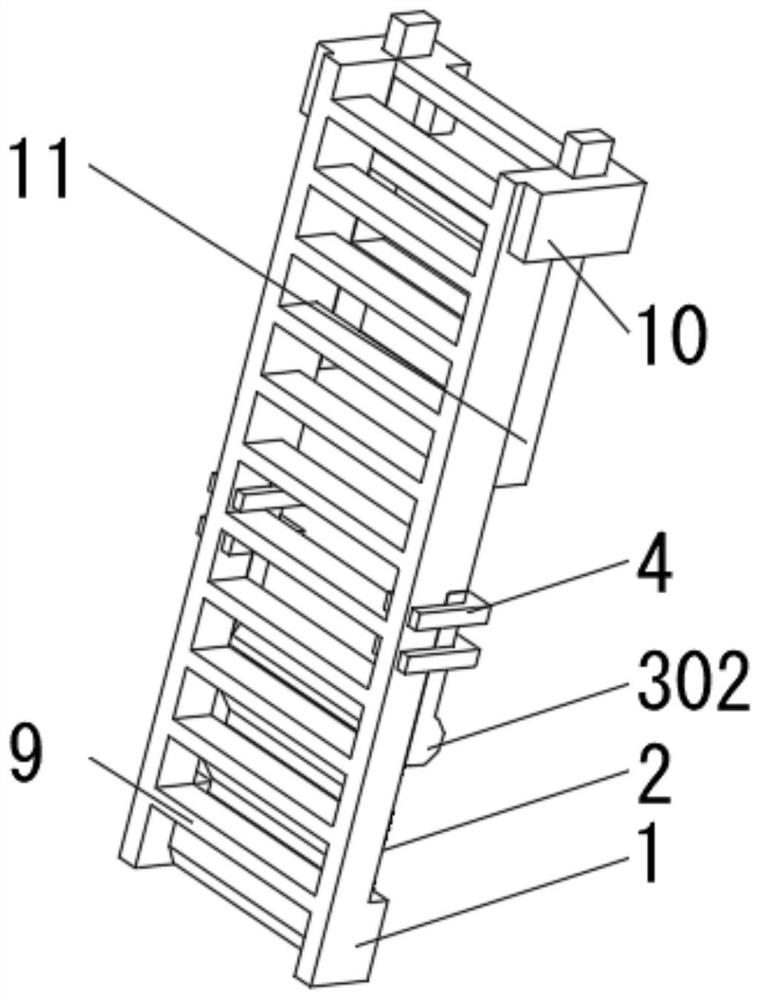
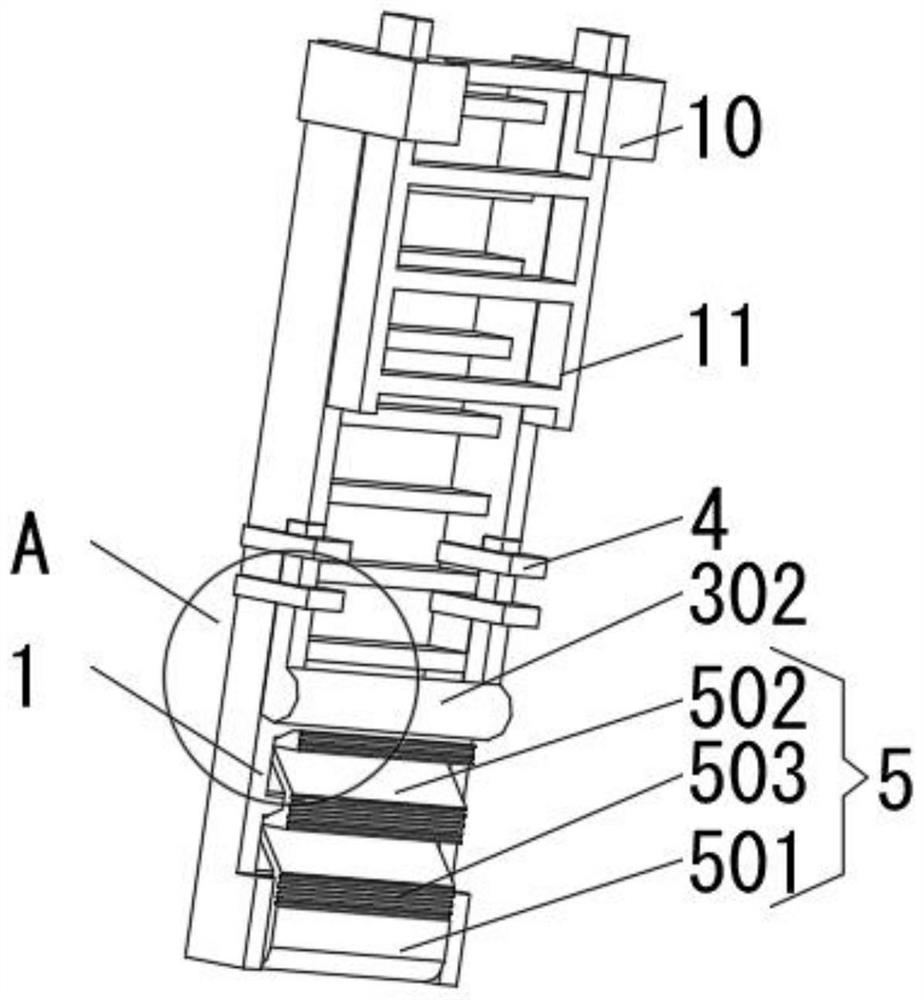
[0028] see Figure 1-2 , the present invention provides a technical solution: an anti-fall ladder with a more stable center of gravity for easy lifting, including a main ladder 1, characterized in that: one side of the main ladder 1 is provided with a chute 2, and the inner wall of the chute 2 slides The pushing device 3 is connected, and the outer side of the pushing device 3 is provided with a limit frame 4. The limit frame 4 is fixedly connected with the main ladder 1. The bottom end of the main ladder 1 near the chute 2 is rotatably connected with a support plate 5. The main ladder 1 An auxiliary ladder 11 is connected to the side of the chute 2 through transmission.

[0029] When in use, the auxiliary ladder 11 rises along the main ladder 1, the angle between the main ladder 1 and the wall becomes smaller, the pushing device 3 slides down along the chute 2, and pushes the support plate 5 away from the main ladder 1 until the supporting The plate 5 is pushed to contact wi...

Embodiment 2

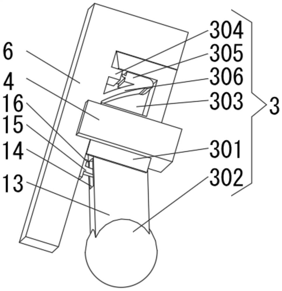
[0031] see Figure 1-4 , the present invention provides a technical solution: an anti-fall ladder with a more stable center of gravity and convenient lifting, including a main ladder 1, a chute 2 is provided on one side of the main ladder 1, and a pushing device is slidingly connected to the inner wall of the chute 2 3. The outer side of the pushing device 3 is provided with a limit frame 4. The limit frame 4 is fixedly connected with the main ladder 1. The bottom end of the side of the main ladder 1 close to the chute 2 is rotatably connected with a support plate 5. The push device 3 is connected to the support plate. 5 sliding connection, the pushing device 3 includes a sliding block 301, the sliding block 301 is slidingly connected with the inner wall of the chute 2, the bottom of the sliding block 301 is equipped with a push ball 302, and the side of the sliding block 301 close to the side plate 6 is provided with a trigger groove 303 One side of the chute 2 is fixedly con...

Embodiment 3

[0034] see Figure 1-4 , the present invention provides a technical solution: on the basis of the second embodiment, the bottom of the sliding block 301 is rotatably connected with a tilting rod 13, the push ball 302 is installed at the bottom of the tilting rod 13, and the side of the tilting rod 13 close to the chute 2 An elastic groove 14 is provided, and one side of the inner wall of the elastic groove 14 is fixedly connected with an inclined spring piece 15 , and one end of the inclined elastic piece 15 away from the elastic groove 14 is fixedly connected with a slide plate 16 , and the slide plate 16 is slidably connected with the chute 2 .

[0035] During use, the height of the ladder is extended after the main ladder 1 is fixed to the wall and the ground, the contact point between the top of the ladder and the wall rises, the angle between the ladder and the wall becomes smaller, and the sliding block 301 presses the convex block 304 and the rotating plate 305 downward. ...


PUM


Abstract

The invention discloses a conveniently lifted anti-falling ladder with a more stable center of gravity and relates to the technical field of ladders. The ladder comprises a main ladder, wherein a chute is formed in one side of the main ladder, a pushing device is slidably connected to the inner wall of the chute, a limiting frame is arranged outside the pushing device in a sleeving manner, the limiting frame is fixedly connected to the main ladder, and a supporting plate is rotatably connected to the end at the bottom on one side, close to the chute, of the main ladder. The conveniently liftedanti-falling ladder with the more stable center of gravity can be reinforced automatically when the ladder is likely to overturn backward as the inclination angle becomes small, so that the problem that the ladder is overturned backward as a result of swing is avoided effectively. A constructor moving to the top of the ladder does not consume a lot of physical power, so that the ladder can ascend, and the ladder ascending efficiency is high. In the process that the constructor climbs upward along the ladder, the ladder ascends automatically, so that the construction efficiency is improved. Meanwhile, the ladder is relatively low in demand on physical power and follow-up construction operation is not affected.

Description

technical field [0001] The invention relates to the technical field of ladders, in particular to a fall-proof ladder with a more stable center of gravity and convenient lifting. Background technique [0002] A ladder is a tool for daily life. The tool is made of two long and thick poles, and a cross bar suitable for climbing is crossed in the middle. It is used for climbing. Ladders are divided into lifting single ladders and lifting ladders. Chinese invention CN109184541A discloses a ladder for aerial work with anti-slip, anti-side fall and dangerous alarm. The ladder cross bar is made into a telescopic structure, which can make the ladder expand and expand laterally according to the demand, increase the lateral projection distance of the ladder, and increase the height of the ladder. The load-bearing area of ​​the center of gravity prevents the ladder from sliding sideways, but when the height of the ladder increases, the inclination angle of the ladder becomes smaller. Si...

Claims


Application Information

Patent Timeline
Patent Type & Authority Applications(China)
IPC IPC(8): E06C1/12E06C7/42E06C7/02E06C7/08
CPCE06C1/12E06C7/02E06C7/08E06C7/423
Inventor 孔怀义
Owner 孔怀义
Learn More