


Quick Research
Generate reliable direction feasibility study reports for your R&D in just a few steps.

Technical Q&A
Discover and master advanced knowledge NOW. Basics, ideas, possibilities, all at once.

Find Solutions
As an expert in R&D theories, this can generate solutions to your technical problems instantly.

Evaluate Feasibility
Analyze your overall solution with one click, know your potential R&D risks in advance.

Monitor Landscape
Get weekly tech updates, stay abreast of the latest tech innovations and key insights.
Automatic wall coating device for building construction
A building construction, automatic technology, applied in the direction of construction, building structure, etc., can solve the problems of low efficiency and safety, and achieve the effect of improving the coating quality
- Summary
- Abstract
- Description
- Claims
- Application Information
AI Technical Summary
Problems solved by technology
Method used
Image

Examples
Embodiment 1
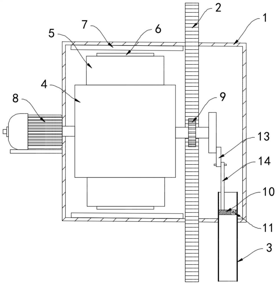
[0020] Such as Figure 1-2 As shown, an automatic wall painting device for building construction includes a housing 1 and a track rod 2. The housing 1 is arranged near the opening on one side of the wall, and the track rod 2 is arranged close to the wall and parallel to the surface of the wall. The track rod 2. It is installed through the housing 1, and the side wall of the track rod 2 is provided with tooth grooves. The lower end of the housing 1 is fixedly connected with the feed pipe 3. The rotating roller 4 rotates in the housing 1. The surrounding side wall of the rotating roller 4 The upper annular array is provided with a plurality of bearing plates 5. The bearing plates 5 are rubber elastic plates. When deformation occurs, the bearing plates 5 can only be bent in the same direction. The ends of the bearing plates 5 that are far away from each other are equipped with permanent magnetic strips. 6. On the side wall of the housing 1, there is a permanent magnet piece 7 rep...
Embodiment 2
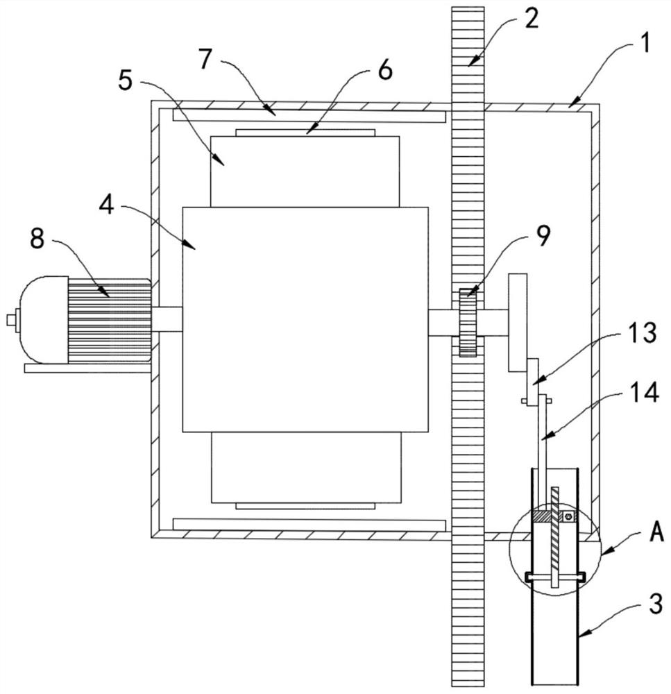
[0026] Such as Figure 3-4 As shown, the difference between this embodiment and Embodiment 1 is that: the feed pipe 3 is provided with a screw rod 17 extending along its axial direction, the upper end of the screw rod 17 passes through the piston block 10 and is threadedly matched with the piston block 10, The lower end of the screw mandrel 17 is fixedly equipped with a plurality of stirring rods 18, and the stirring rods 18 are rotatably connected with the inner sidewall of the feed pipe 3.
[0027] In this embodiment, during the reciprocating movement of the piston block 10 up and down, it drives the threaded screw 17 to rotate, and the stirring rod 18 rotates to stir the cement material in the feed pipe 11 to prevent it from clogging and agglomerating. , causing the problem of feed pipe clogging.
PUM
 Abstract
Description
Claims
Application Information
 - R&D Engineer
- R&D Manager
- IP Professional
- Industry Leading Data Capabilities
- Powerful AI technology
- Patent DNA Extraction
Browse by: Latest US Patents, China's latest patents, Technical Efficacy Thesaurus, Application Domain, Technology Topic, Popular Technical Reports.
© 2024 PatSnap. All rights reserved.Legal|Privacy policy|Modern Slavery Act Transparency Statement|Sitemap|About US| Contact US: help@patsnap.com