Automatic coupling probe for ultrasonic department

An automatic coupling, ultrasonic technology, used in ultrasonic/sonic/infrasonic diagnosis, medical science, sonic diagnosis, etc., can solve the problems of inconvenient and quick disassembly, cumbersome disassembly, easy damage, etc., to prevent accumulation of dust and adjust operation. Simple and effective to meet the needs of use

Inactive Publication Date: 2020-09-29
崔勤皓
View PDF0 Cites 4 Cited by
  • Summary
  • Abstract
  • Description
  • Claims
  • Application Information

AI Technical Summary

Problems solved by technology

[0003] However, most of the ultrasonic automatic coupling probes currently on the market have the problems of lack of protection and easy damage, which increases the cost of use, and is easy to accumulate dust, which affects the use of the probe. Disassembly and assembly will affect the maintenance or replacement of the automatic coupling probe. In addition, during the inspection, the couplant tube is too long to facilitate the movement of the probe, which increases labor intensity and affects inspection efficiency.

Method used


Image

  • Automatic coupling probe for ultrasonic department
  • Automatic coupling probe for ultrasonic department
  • Automatic coupling probe for ultrasonic department

Examples


Embodiment 1

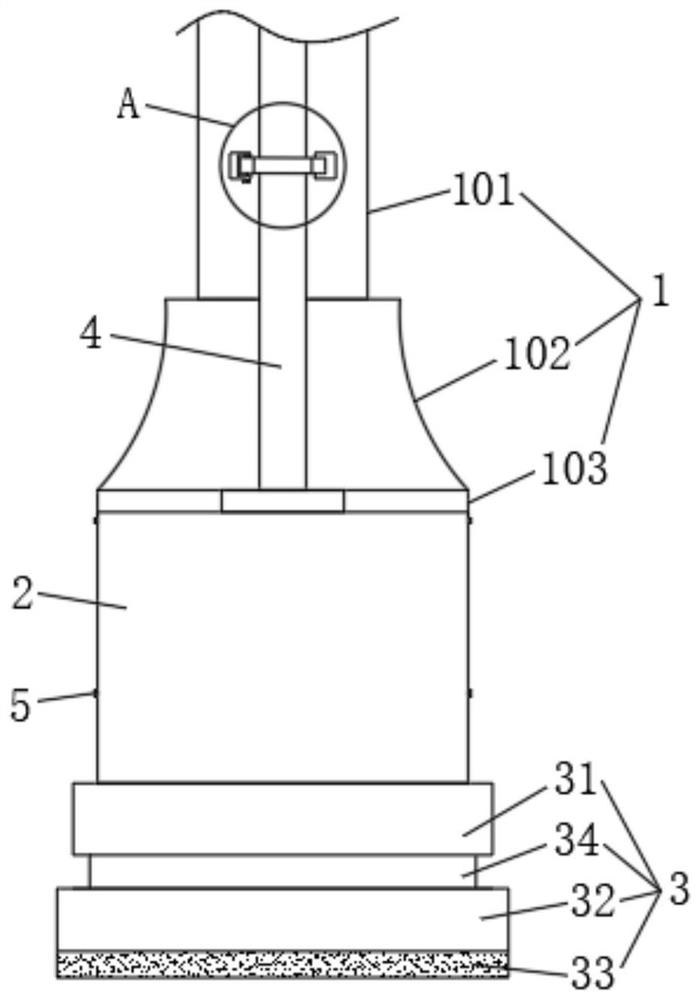
[0042] see Figure 1-Figure 15 shown, where figure 1 It is a schematic structural diagram of an ultrasonic automatic coupling probe provided by an embodiment of the present invention. It can be seen from the figure that the automatic coupling probe includes a detection component, a protection mechanism 3 sleeved at the end of the detection component, and a connection between the detection component and The matching component of the protection mechanism 3, the detection component includes the probe body 1 and the automatic coupling mechanism 2 clamped by the connecting component, and the automatic coupling mechanism 2 is clamped at the bottom of the probe body 1;

[0043] The protection mechanism 3 includes an outer frame 31 and a sleeve frame 32 sleeved on the end of the outer frame 31. The outer frame 31 is provided with a movable groove 34, and the edge of one end of the sleeve frame 32 extends inward to form a movable part 35, and the movable part 35 It fits inside the mov...

Embodiment 2

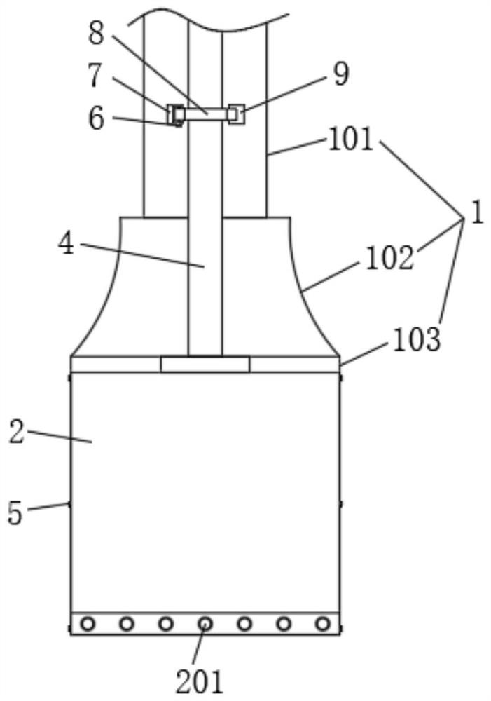
[0067] see Figure 15As shown, the mating assembly includes installation holes opened on both sides of the probe body 1 and the automatic coupling mechanism 2, and insertion rods 21 symmetrically screwed to both sides of the protection mechanism 3. The insertion rods 21 penetrate the interior of the installation holes, and the insertion rods 21 A twisting rod is installed at one end outside the protection mechanism 3 , and there are at least four mounting holes and inserting rods 21 , and the four inserting rods 21 correspond to the four mounting holes one by one.

[0068] Specifically, in this implementation, when it is necessary to use the probe, the medical staff can first screw the insertion rod 21 through the screw rod to unscrew the insertion rod 21 from the mounting hole, and then pull the protection mechanism 3 to release the protection mechanism 3 from the probe. The body 1 and the outer part of the automatic coupling mechanism 2 are removed, and then the medical pers...


PUM


Abstract

The invention discloses an automatic coupling probe for an ultrasonic department, and relates to the technical field of medical equipment. The automatic coupling probe for the ultrasonic department comprises a detection assembly, a protection mechanism sleeving the end part of the detection assembly, and a cooperation assembly for connecting the detection assembly and the protection mechanism, wherein the detection assembly comprises a probe body and an automatic coupling mechanism which are connected in a clamped mode through a connecting assembly; the protection mechanism comprises an outerframe and a sleeve frame arranged at the end part of the outer frame in a sleeving mode; a movable groove is formed in the outer frame; the edge of one end of the sleeve frame extends inwards to forma movable part; and the movable part is matched with the interior of the movable groove to form a movable mechanism. The adjustable protection mechanism is arranged and can cover the probe, and the buffering purpose is achieved when the probe falls accidentally, so that the probe is protected, the probe is effectively prevented from being damaged due to accidental falling, dust can be prevented from being accumulated on the probe, the service life of the probe is prolonged, and the use cost of the probe is reduced.

Description

technical field [0001] The invention belongs to the technical field of medical equipment, and in particular relates to an automatic coupling probe for an ultrasound department. Background technique [0002] In clinical medical treatment, it is often necessary to check the patient's body through a detection device, such as ultrasonic examination. Ultrasonic examination uses waves generated by ultrasound to propagate in the human body. It is a method to diagnose diseases by weakening the law, and the probe is used for the transmission and reception of ultrasonic waves. In ultrasonic testing, the probe is a transducer that uses the piezoelectric effect of materials to convert electrical energy and sound energy. [0003] However, most of the ultrasonic automatic coupling probes currently on the market have the problems of lack of protection and easy damage, which increases the cost of use, and is easy to accumulate dust, which affects the use of the probe. Disassembly and assem...

Claims


Application Information

Patent Timeline
Patent Type & Authority Applications(China)
IPC IPC(8): A61B8/00
CPCA61B8/4281A61B8/4411A61B8/4455
Inventor 崔勤皓袁妮莎
Owner 崔勤皓
Why Eureka
Try Eureka