Bias working point automatic control system based on temperature drift compensation

An automatic control system and offset working point technology, which is applied in the transmission system, electromagnetic wave transmission system, optics, etc., can solve the problem of link performance deterioration, the pilot method cannot achieve stable working point, and it is difficult to meet high-precision arbitrary offset Work point stability requirements and other issues

Active Publication Date: 2020-09-25
NO 34 RES INST OF CHINA ELECTRONICS TECH GRP
View PDF8 Cites 1 Cited by
  • Summary
  • Abstract
  • Description
  • Claims
  • Application Information

AI Technical Summary

Problems solved by technology

However, in practical engineering applications, the operating point of the Mach-Zehnder modulator is easily affected by environmental changes, such as temperature, pressure, and mechanical vibration, which will cause the shift of the operating point of the modulator, resulting in the deterioration of link performance.
The existing methods for stabilizing the MZM operating point mainly include the pilot method and the optical power control method, but the pilot method cannot achieve the stability of any operating point and the pilot will cause intermodulation near the carrier, which will affect the phase purity of the signal
The optical power control method is affected by temperature changes, and the control accuracy is not high, so the existing two methods are difficult to meet the stable requirements of high-precision arbitrary bias operating points

Method used


Image

  • Bias working point automatic control system based on temperature drift compensation
  • Bias working point automatic control system based on temperature drift compensation

Examples


Embodiment Construction

[0027] Embodiments of the present invention are described in detail below, examples of which are shown in the drawings, wherein the same or similar reference numerals designate the same or similar elements or elements having the same or similar functions throughout. The embodiments described below by referring to the figures are exemplary and are intended to explain the present invention and should not be construed as limiting the present invention.

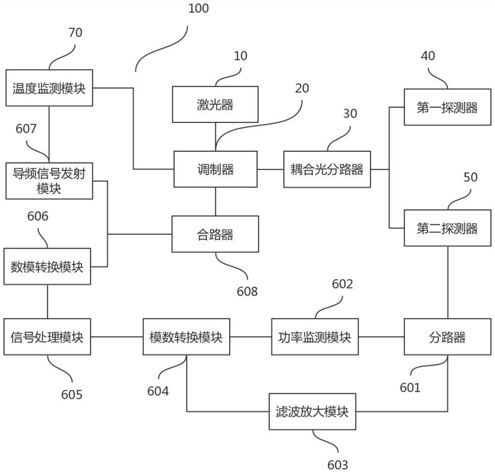
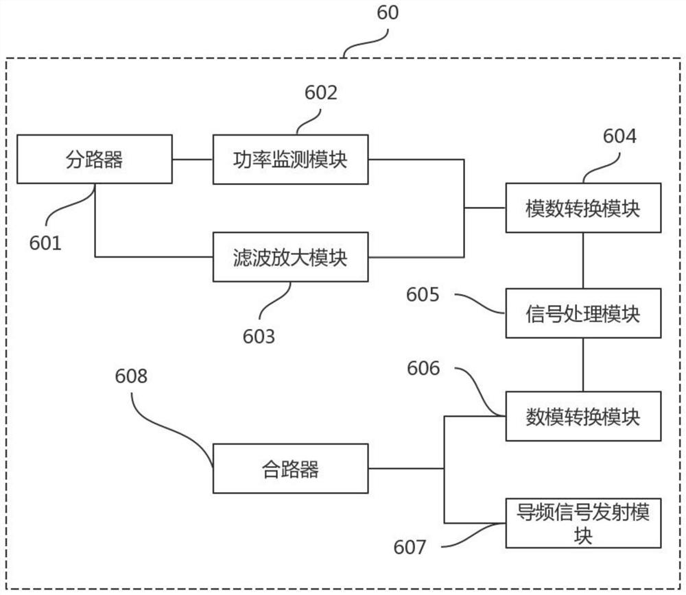
[0028] see figure 1 , figure 1 It is a structural schematic diagram of the bias operating point automatic control system 100 based on temperature drift compensation in the present invention. The present invention provides an automatic bias operating point control system 100 based on temperature drift compensation, including a laser 10, a modulator 20, a coupling optical splitter 30, a first detector 40, a second detector 50, and a feedback loop module 60 and a temperature monitoring module 70, the laser 10 is connected to the o...


PUM


Abstract

The invention discloses a bias working point automatic control system based on temperature drift compensation. A method comprises the steps: monitoring and recording the output optical power of the modulator through a feedback loop module; calculating the ratio of the output optical power to the maximum output optical power to serve as the measurement value of a bias working point at the initial temperature and monitoring the fundamental wave and second harmonic components of a pilot signal; performing calculating to obtain a modulator bias phase coefficient and a phase coefficient corresponding to each power ratio, taking the phase coefficient at the moment as a direct-current bias phase coefficient standard value, completing initialization work of a modulator bias working point, and closing the pilot signal; enabling the temperature monitoring module to detect the real-time temperature of the modulator, and sending a control signal to the feedback loop module when the temperature changes; enabling the feedback loop module to receive the control signal, starting a pilot method to correct the working point, and continuously adjusting the bias voltage until the standard value driftsclose to zero, so the stability of any bias working point is realized, and the influence of temperature change is basically avoided.

Description

technical field [0001] The invention relates to the technical field of modulator control, in particular to an automatic control system of a bias operating point based on temperature drift compensation. Background technique [0002] Microwave photonic links have important applications in radar systems, radio frequency optical fiber transmission, microwave signal generation, optical fiber sensing and other fields. Among them, radio frequency optical fiber transmission (ROF) is a method that modulates radio frequency signals to optical carriers and transmits them using optical fibers. Compared with coaxial cable transmission, ROF has the advantages of light weight, low loss, high speed and large capacity. A basic ROF link based on an external modulator is composed of a laser, an external modulator, and a photodetector. The external modulator is an important device for realizing electro-optic conversion, compared to directly loading a radio frequency signal to a laser to achieve...

Claims


Application Information

Patent Timeline
Patent Type & Authority Applications(China)
IPC IPC(8): H04B10/50G02F1/03
CPCH04B10/503H04B10/505G02F1/0327
Inventor 朱宏韬杨万里尹怡辉熊汉林陈协助
Owner NO 34 RES INST OF CHINA ELECTRONICS TECH GRP
Why Eureka
Try Eureka