Backflow prevention device

A backflow prevention device and a technology for stopping flow

Pending Publication Date: 2020-09-25
MCC5 GROUP CORP SHANGHAI
View PDF0 Cites 0 Cited by
  • Summary
  • Abstract
  • Description
  • Claims
  • Application Information

AI Technical Summary

Problems solved by technology

[0005] The existing anti-backflow devices generally have the disadvantages of complex structure, inconvenient operation, and unstable anti-backflow effect

Method used


Image

  • Backflow prevention device
  • Backflow prevention device
  • Backflow prevention device

Examples


Embodiment Construction

[0023] The structure of the present invention will be further described below in conjunction with the accompanying drawings and specific embodiments, but it is not intended as a limitation of the present invention.

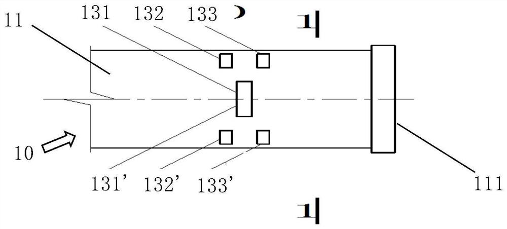
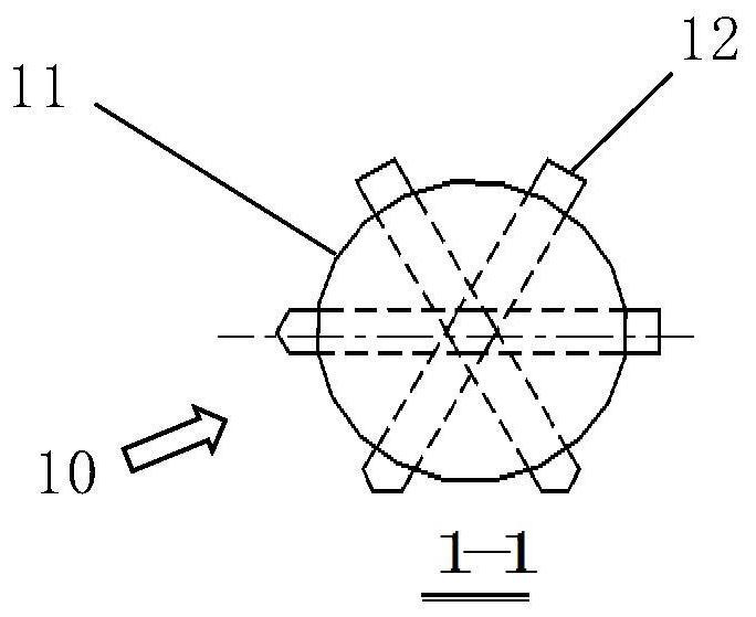
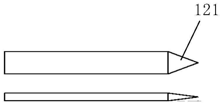
[0024] Such as figure 1 and figure 2 As shown, a backflow prevention device of the present invention includes a stop valve 10, and the stop valve 10 is provided with a circular tubular valve body 11. On the tube wall of the valve body 11, multiple pairs of sockets 131 and 131', 132 and 132', 133 and 133' may be provided along the circumference of the tube wall, each pair of sockets 131 and 131', 132 and 132' , 133 and 133' are arranged on the pipe wall on the opposite side of the valve body 11, and can be used for inserting and passing out of a valve gate 12. Therefore, a plurality of valve gates 12 can be plugged on the pipe wall of the valve body 11 . figure 2 Shown is the assembly form when three valve gates 12 are arranged on the stop valve 10 of the pres...


PUM


Abstract

The invention discloses a backflow prevention device. The backflow prevention device includes a stop valve; the stop valve includes a tubular valve body and a plurality of valve gates inserted on thepipe wall of the valve body; the upper and lower ends of the valve body are used to be tightly connected between a pipe column to be poured and a pouring material delivery pipe; when pouring, the valve gates are pulled out from the valve body, so that the pouring material in the pouring material conveying pipe is lifted into the pipe column through the valve body; and after the pouring is completed, and when the pouring material delivery pipe is disassembled, the valve gates are inserted and passed out of the valve body to prevent the pouring material in the pipe column from gushing down fromthe valve body. The backflow prevention device disclosed by the invention is simple to manufacture, can be used repeatedly, can effectively improve the jacking efficiency, and can reduce a large amount of manual rework.

Description

technical field [0001] The invention relates to the technical field of pumping machinery, in particular to a backflow prevention device. Background technique [0002] In the building construction industry, it is often faced with the construction that concrete (concrete) needs to be lifted (pumped) into the steel pipe column for pouring, so as to make the steel pipe concrete column. [0003] Among them, the pumping equipment includes a ground pump and a concrete delivery pipe connected to the ground pump. The concrete delivery pipe is connected to the hole at the lower end of the steel pipe column to realize the operation of lifting the concrete in the concrete delivery pipe to the steel pipe column for pouring. [0004] When the jacking operation is completed, the concrete conveying pipe needs to be dismantled from the opening at the lower end of the steel pipe column. At this time, the concrete in the steel pipe column has not yet solidified, and under the action of its ow...

Claims


Application Information

Patent Timeline
Patent Type & Authority Applications(China)
IPC IPC(8): F16K3/02F16K3/314F16K3/30F16K27/04F16K15/00E04G21/02
CPCE04G21/02F16K3/029F16K3/30F16K3/314F16K15/00F16K27/044
Inventor 王鹏
Owner MCC5 GROUP CORP SHANGHAI
Why Eureka
Try Eureka