
Corrugated film hole with branch holes

A technology of air film holes and corrugated shapes, applied in the direction of blade support components, engine components, machines/engines, etc., can solve the problems that the shape cannot be processed qualifiedly, and there are few complicated special-shaped hole test verifications, etc., to achieve a good air film Coverage area, convenient processing, and the effect of reducing momentum

Active Publication Date: 2020-09-25
CIVIL AVIATION UNIV OF CHINA
View PDF8 Cites 1 Cited by
  • Summary
  • Abstract
  • Description
  • Claims
  • Application Information

AI Technical Summary

Problems solved by technology

In recent years, our country has also studied a variety of special-shaped holes with branch holes, including ingot holes and heart-shaped holes. It is the designed shape that cannot be processed satisfactorily

Method used

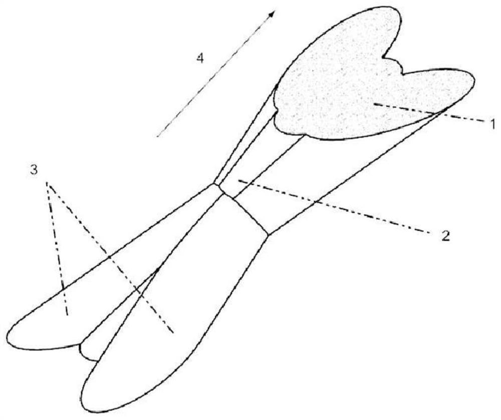
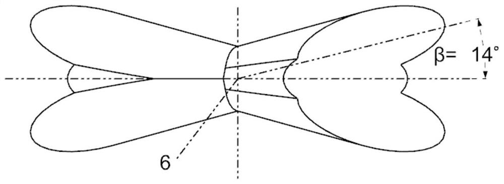
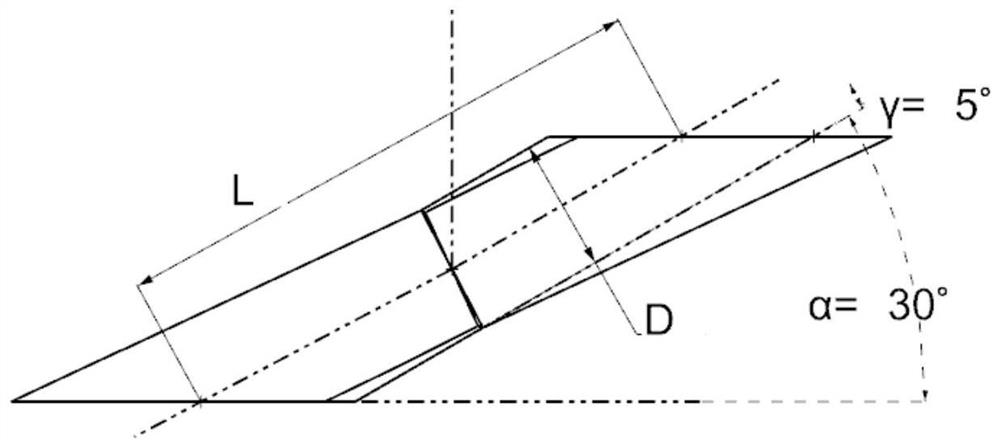

Image

  • Corrugated film hole with branch holes
  • Corrugated film hole with branch holes
  • Corrugated film hole with branch holes

Examples


Embodiment 1

[0029] like figure 1 , as shown in Fig. 2, the corrugated gas film hole with branch hole provided by the present embodiment is double corrugated hole, comprises main hole 2 and two branch holes; The second half section 5 of the two branch holes is arranged on the left and right sides of the front part of the main hole 2, and has a spanwise expansion and backward inclination; the second half section 5 of the two branch holes communicates with the rear part of the main hole 2 , the airflow 4 flows to the outlet section 1 similar to a special-shaped hole along the direction indicated by the arrow.

Embodiment 2

[0031] like image 3 , as shown in Figure 4, the corrugated gas film hole with branch holes provided in this embodiment is a single corrugated hole, including the main hole 2 and the second half section 5 of the two branch holes; the second half section 5 of the two branch holes is connected with the main hole The rear parts of 2 communicate with each other, which is the only difference between the single corrugated hole and the above-mentioned double corrugated hole, mainly due to processing considerations. In the case of limited processing equipment, in order to reduce the damage of the back substrate during laser processing or when the high-temperature component is a multi-layer composite material, the number of processing in a specific area needs to be reduced. Single corrugated holes are used. The inlet cross section 7 of the single corrugated hole is elliptical consistent with the traditional cylindrical hole.

[0032] In the above-mentioned double corrugated hole and s...


PUM


Abstract

The invention discloses a corrugated film hole with branch holes. The corrugated film hole is divided into double-corrugated hole and single-corrugated hole; the double-corrugated hole comprises a main hole and two branch holes; each branch hole is composed of a branch hole front half section and a branch hole rear half section; and the single-corrugated hole comprises a main hole and two branch hole rear half sections. Compared with a cylindrical hole, the corrugated film hole with the branch holes provided by the invention has the advantages that the film cooling performance can be greatly improved, the cooling effect is better and more stable under the low air blowing ratio compared with an international advanced nekomimi hole, and the cooling effect is greatly improved under the high air blowing ratio, so that the film coverage is more balanced and effective; the hole pattern structure complexity is greatly simplified, the machining difficulty is reduced, the machining fault tolerance degree is increased, and a contribution is made to landing of the advanced cooling technology in China.

Description

technical field [0001] The invention belongs to the technical field of gas film cooling of hot end components in a gas turbine power device, in particular to a corrugated gas film hole with branch holes. Background technique [0002] Increasing the inlet temperature of the turbine stage can increase the thrust-to-weight ratio and thermal efficiency of the aeroengine. With the increasing requirements of aero-engines on the thrust-to-weight ratio, etc., the temperature before the engine turbine is further increased. At present, the gas temperature before the turbine of an engine with a thrust-to-weight ratio of 10 is about 1940K. In the future, civil aviation airliners may reach a thrust-to-weight ratio of 15, and the gas temperature before the turbine will be about 2150K. It is 2100K ~ 2300K. The continuous increase of gas temperature in front of the turbine has exceeded the limit that the material can withstand. In order to make the hot end parts of the turbine work effect...

Claims


Application Information

Patent Timeline
IPC IPC(8): F01D25/12F01D5/18
CPCF01D25/12F01D5/186F05D2260/202
Inventor 杨晓军常嘉文刘智刚靳晓宇陈羽刘文博柳笑寒周昊旻
Owner CIVIL AVIATION UNIV OF CHINA
Learn More