Tubular connecting piece and cast-in-place concrete built-in thermal insulation wall body

A technology of connectors and pipe bodies, which is applied in the field of tubular connectors and cast-in-place concrete built-in thermal insulation walls, can solve the problems that the tubular connectors cannot be connected with steel wire mesh, so as to avoid detachment from the insulation layer, strengthen the firmness, reduce The effect of heat loss

Pending Publication Date: 2020-09-25
山东赛昌新型材料有限公司
View PDF0 Cites 1 Cited by
  • Summary
  • Abstract
  • Description
  • Claims
  • Application Information

AI Technical Summary

Problems solved by technology

[0003] The invention provides a tubular connector and a built-in thermal insulation wall of cast-in-place concrete, which solves the problem that the tubular connector cannot be connected with the steel wire mesh in the prior art

Method used


Image

  • Tubular connecting piece and cast-in-place concrete built-in thermal insulation wall body
  • Tubular connecting piece and cast-in-place concrete built-in thermal insulation wall body
  • Tubular connecting piece and cast-in-place concrete built-in thermal insulation wall body

Examples


Embodiment 1

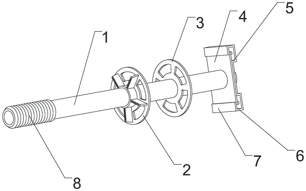
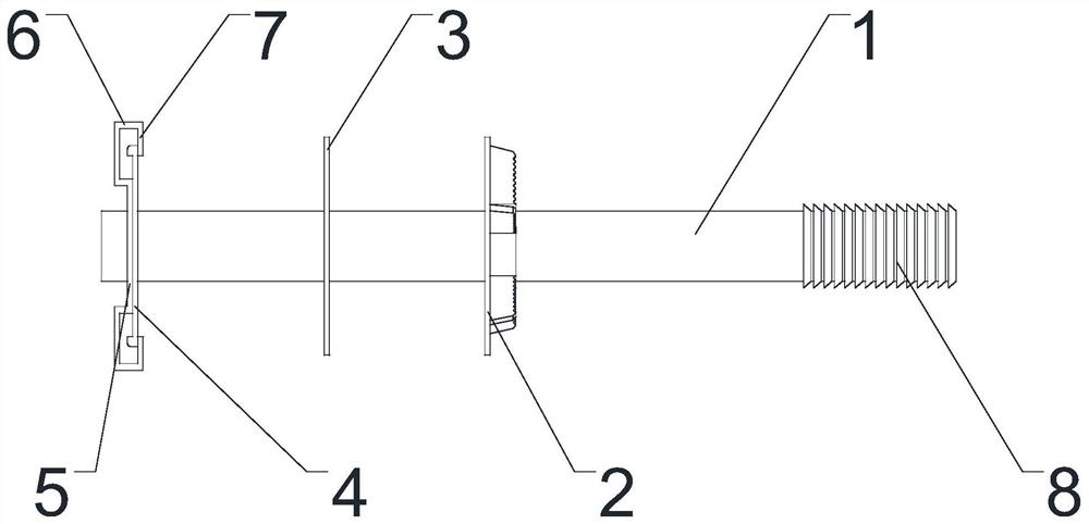
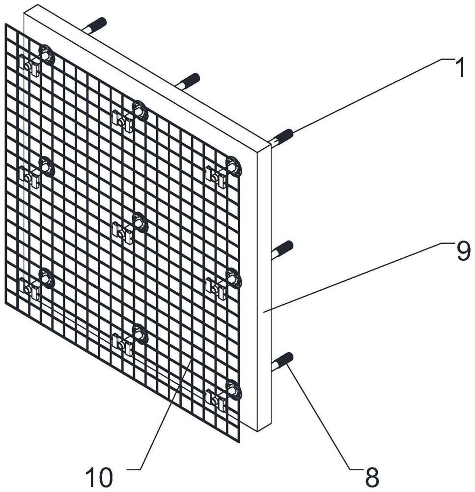
[0040] Such as Figure 1-4As shown, a tubular connector includes a tube body 1, the axial channel of the tube body 1 runs through the tube body 1 to form openings at both ends of the tube body 1, and the outer wall of the tube body 1 is provided with a first limiting piece 2, a second The second limiting piece 3 and the connecting mechanism, the connecting mechanism and the first limiting piece 2 are respectively located on both sides of the second limiting piece 3 . When the present invention is in use, the first limiting piece 2 and the second limiting piece 3 clamp the heat preservation board, so that the heat preservation plate is fixedly connected with the pipe body 1, and the pipe body 1 is connected with the steel wire mesh sheet 10 through a connecting mechanism, and the steel wire mesh sheet 10 is located in the outer wall layer 12, so the steel wire mesh sheet 10 can provide pulling force to the outer wall layer 12, strengthen the firmness of the combination of the o...

Embodiment 2

[0050] Such as Figure 7 As shown, the difference between this embodiment and Embodiment 1 is that the connection mechanism includes a first limit rod 13 that is fixedly connected with the tube body 1 or integrally formed, and the end of the first limit rod 13 is provided with a second limit rod. Bit pole 14. The first limiting rod 13 is perpendicular to the axis of the pipe body 1 , and the second limiting rod 14 is perpendicular to the first limiting rod 13 . During use, the first limiting rod 13 pulls the steel wire mesh sheet to the insulation layer 9 , and the second limiting rod 14 can prevent the steel wire of the steel mesh sheet from breaking away from the first limiting rod 13 .

Embodiment 3

[0052] The difference between this embodiment and Embodiment 1 is that the second limiting piece 3 is fixedly connected or integrally formed with the tube body 1, and the first end piece 4 and / or the first limiting piece 2 and the tube body 1 can be Disconnect the connection. The second limiting piece 3 is fixedly connected or integrally formed with the tube body 1, which increases the overall stability of the present invention. The first end piece 4 and the first limiting piece 2 are detachably connected with the tube body 1, which is convenient for the tube body 1 After the pipe body 1 passes through the heat preservation board, the first limiting piece 2 and the end piece are sequentially sleeved on the pipe body 1 to limit the heat preservation board. The second limiting piece 3 is integrally formed or fixedly connected with the first end piece 4 . The outer wall of the pipe body 1 is provided with threads, and the first limiting piece 2 and / or the first end piece 4 is th...


PUM


Abstract

The invention relates to the field of building template connection supporting, and relates to a tubular connecting piece. The tubular connecting piece solves the problem that a tubular connecting piece is not connected with a steel wire mesh piece in the prior art. The tubular connecting piece comprises a pipe body. An axial channel of the pipe body penetrates through the pipe body to form openings in the two ends of the pipe body. A first limiting piece, a second limiting piece and a connecting mechanism are arranged on the outer side wall of the pipe body. The connecting mechanism and the first limiting piece are correspondingly located on two sides of the second limiting piece. The steel wire mesh piece can apply a tensile force to an outer wall layer, the firmness of the combination ofthe outer wall layer and a thermal insulation layer is enhanced, and the outer wall layer is prevented from being separated from the thermal insulation layer. The cast-in-place concrete built-in thermal insulation wall body comprises the inner wall layer, the outer wall layer, the thermal insulation layer located between the inner wall layer and the outer wall layer and a tubular connecting piece. The pipe body penetrates through the inner wall layer, the thermal insulation layer and the outer wall layer. The steel wire mesh piece is arranged in the outer wall layer. A first end piece and a second end piece are located on the two sides of the steel wire mesh piece correspondingly. The thermal insulation layer is located between the first limiting piece and the second limiting piece.

Description

technical field [0001] The invention relates to the field of connection and support of building templates, in particular to a tubular connector and a built-in thermal insulation wall of cast-in-place concrete. Background technique [0002] The cast-in-place concrete built-in thermal insulation wall refers to the wall made by setting up formwork on site, binding steel bars, pouring concrete, curing, and removing formwork. The cast-in-place concrete built-in thermal insulation wall structure is to improve the thermal insulation performance. The wall with thermal insulation layer is set in the cast-in-situ concrete built-in thermal insulation wall, which has the structure of inner wall layer-insulation layer-external wall layer. The tubular connector for cast-in-place concrete built-in thermal insulation walls previously applied by the applicant includes a pipe body. The axial channel of the pipe body runs through the pipe body to form openings at both ends of the pipe body. Th...

Claims


Application Information

Patent Timeline
Patent Type & Authority Applications(China)
IPC IPC(8): E04B2/00E04B1/76
CPCE04B1/76E04B1/7608E04B2/00
Inventor 刘文起
Owner 山东赛昌新型材料有限公司
Why Eureka
Try Eureka