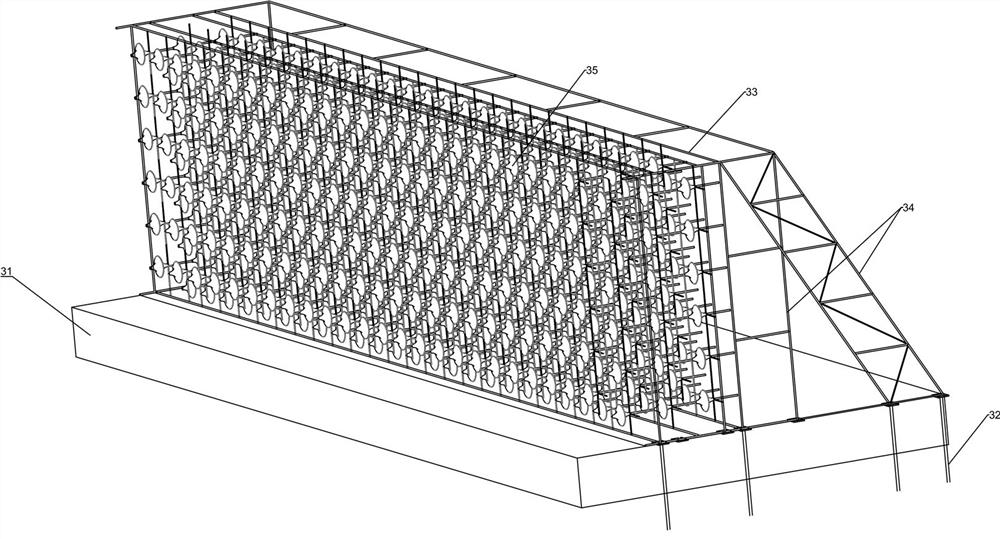
Overflow dam flood discharge underflow flushing preventing energy dissipation wall
An overflow dam and anti-scouring technology, which is applied in water conservancy projects, sea area projects, coastline protection, etc., can solve problems such as the difficulty of wear and repair, reduce erosion and wear, reduce construction and maintenance costs, and increase the service life of the project Effect
- Summary
- Abstract
- Description
- Claims
- Application Information
AI Technical Summary
Problems solved by technology
Method used
Image
Examples
Embodiment 2
[0045] Embodiment 2: On the basis of Embodiment 1, flow guide ribs are further distributed on the flow guide base 351 of each energy dissipation unit 35 along the direction of its concave cone surface 3512, as shown in Figure 14 As shown, a straight diversion groove 3515 is formed in the area between adjacent diversion ribs, and the area located in the adjacent straight diversion groove 3515 forms a lateral thrust on the diversion base 351 due to changes in the impact pressure of the water flow, thereby forming The energy dissipation units 35 are vibrated and transmitted to the main frame 33 to dissipate energy.
Embodiment 3
[0046] Embodiment 3: On the basis of the above 2, further design makes the main part of the inner threaded rod 352 be prismatic, so that the threaded rod 352 and each flow guide base 351 can rotate synchronously.
[0047] Such as Figure 15 and Figure 16 As shown, the inner shaft sleeve 358 is used to support the end of the flow guide base 351 to provide sufficient pressure to make it stable, and the outer side of the inner shaft sleeve 358 is fitted with the locking sleeve 354, and the two are snapped together by the inner ring step and can be Rotate, the outer side of the lock sleeve 354 is fixed by the side link 355 .
[0048] Simultaneously, there are guide ribs distributed along the direction of the spiral direction of the guide base 351 along its concave cone surface 3512, and a spiral guide groove 3516 is formed in the area between adjacent guide ribs, and the water flow impacts the guide base 351 to make it Rotate, the adjacent flow guide bases 351 on the same inner...
Embodiment 4
[0049] Embodiment 4: There is a similar design to Embodiment 3, so that the main body part of the inner wear rod 352 is prismatic, or a plane is provided on the side of the cylindrical main part or a protruding or concave position or keyway is arranged in the axial direction, and in Wear the inner bushing 358 of pull rod 351 outer suit, inner bushing 358 central hole inwall has keyway 3514 or key, as Figure 15 and Figure 16 As shown, the tie rod 352 and each flow guide base member 351 can rotate synchronously and integrally.
PUM
 Abstract
Description
Claims
Application Information
 - R&D Engineer
- R&D Manager
- IP Professional
- Industry Leading Data Capabilities
- Powerful AI technology
- Patent DNA Extraction
Browse by: Latest US Patents, China's latest patents, Technical Efficacy Thesaurus, Application Domain, Technology Topic, Popular Technical Reports.
© 2024 PatSnap. All rights reserved.Legal|Privacy policy|Modern Slavery Act Transparency Statement|Sitemap|About US| Contact US: help@patsnap.com


