Automatic threading equipment for annealing device, and annealing device

An annealing device and automatic wearing technology, applied in the direction of heat treatment equipment, furnace types, furnaces, etc., can solve problems such as burns, whipping burns, etc.

Inactive Publication Date: 2020-09-25
ZHUHAI RONSEN SUPER MICRO WIRE CO LTD
View PDF0 Cites 0 Cited by
  • Summary
  • Abstract
  • Description
  • Claims
  • Application Information

AI Technical Summary

Problems solved by technology

During the threading process, due to the long length of the steel strand, the temperature in the annealing furnac

Method used


Image

  • Automatic threading equipment for annealing device, and annealing device
  • Automatic threading equipment for annealing device, and annealing device
  • Automatic threading equipment for annealing device, and annealing device

Examples


Embodiment Construction

[0027] Embodiment of automatic threading device:

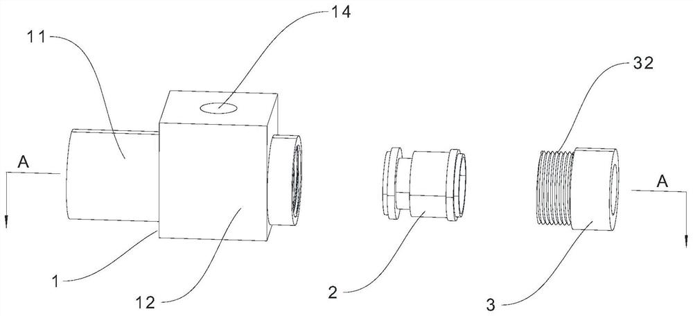
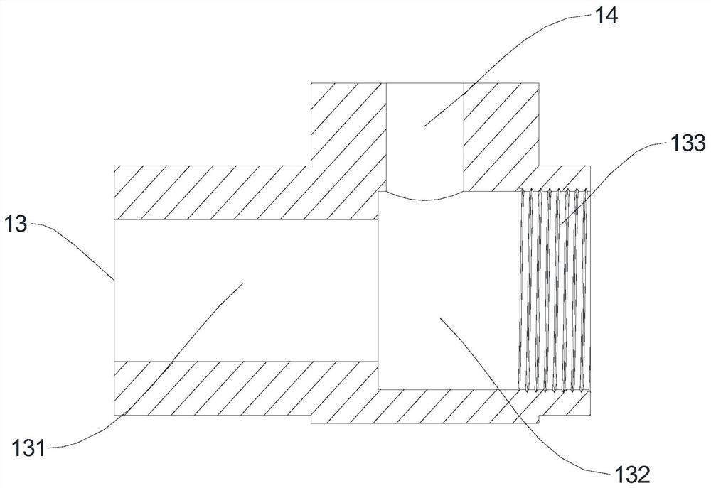
[0028] see Figure 1 to Figure 3 and Figure 5 , The automatic threading device provided in this embodiment includes a shell main body 1 , a functional part 2 and a fastener 3 connected in sequence. The casing main body 1 includes a first main body 11 and a second main body 12 that communicate with each other, and a first through hole 13 is opened along the axial direction of the first main body 11, and an air inlet 14 is opened on the second main body 12. The axes of the through hole 13 and the air inlet hole 14 are perpendicular. The first through hole 13 includes a first communication section 131 and a second communication section 132 , and a first end of the second communication section 132 communicates with the first communication section 131 . The fastener 3 is fixed on the second end of the second communication section 132 , and a third through hole 31 is opened along the axial direction of the fastener 3 , and the t...


PUM


Abstract

The invention provides automatic threading equipment for an annealing device, and the annealing device. The automatic threading equipment comprises a shell body, a functional part and a fastener whichare connected in sequence; the shell body comprises a first main body and a second main body which communicate with each other, a first through hole is formed in the first main body, an air inlet hole is formed in the second main body, and the first through hole is perpendicular to the axis of the air inlet hole; the functional part is arranged in a second communicating section, a second throughhole and a ring groove are formed in the functional part, and the ring groove communicates with the air inlet hole; and an air outlet hole is formed in the functional part, communicates with the second through hole, and outputs an air flow into the second through hole from the ring groove. The annealing device comprises the automatic threading equipment and comprises an annealing device body, andan annealing pipe is arranged in the annealing device body and communicates with the first main body. The automatic threading equipment can achieve automatic threading of a bare copper wire in the annealing pipe, and the scalding accident brought by manual threading can be avoided.

Description

technical field [0001] The invention relates to the technical field of enameled wire production equipment, in particular to an automatic threading equipment used for an annealing device and an annealing device. Background technique [0002] In the enameled wire production process, annealing is an essential process. After the bare copper wire is annealed, the bare copper wire is processed into enameled wire. The purpose of annealing is to reduce the hardness and residual stress of the bare copper wire, reduce the deformation and crack tendency of the bare copper wire, improve the machinability of the bare copper wire, stabilize the size of the bare copper wire, refine the grain of the bare copper wire, and adjust the structure , Eliminate organizational defects. At present, the commonly used annealing device in the bare copper wire production process is a tubular annealing furnace, and an annealing tube is arranged in the tubular annealing furnace. When using the annealing ...

Claims


Application Information

Patent Timeline
IPC IPC(8): C21D9/63C21D1/26C22F1/08
CPCC21D1/26C21D9/562C21D9/63C22F1/08
Inventor 杨楚丙佘松灿李成杰
Owner ZHUHAI RONSEN SUPER MICRO WIRE CO LTD
Why Eureka
Try Eureka