
Product positioning device for product packaging

A positioning device and product packaging technology, applied in packaging and other directions, can solve the problems of low product packaging efficiency and low work efficiency, and achieve the effect of increasing packaging efficiency

Inactive Publication Date: 2020-09-25
泉州市高谦机械产品有限公司
View PDF9 Cites 0 Cited by
  • Summary
  • Abstract
  • Description
  • Claims
  • Application Information

AI Technical Summary

Problems solved by technology

[0003] When packaging products, it is often necessary to use a product positioning device to position the product. The current positioning device is generally simple in structure, and the product is clamped and fixed by the cylinder. After the product is packaged, it is often necessary to stop the machine and remove the product. Only then can the product be placed again for processing, and the work efficiency is low. The existing product positioning device for product packaging is not easy to circulate the product, resulting in low product packaging efficiency.

Method used


Image

  • Product positioning device for product packaging
  • Product positioning device for product packaging
  • Product positioning device for product packaging

Examples


Embodiment 1

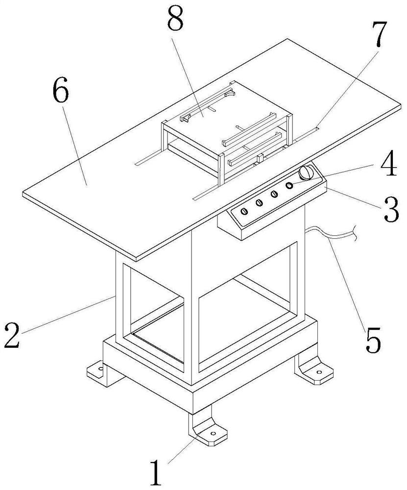
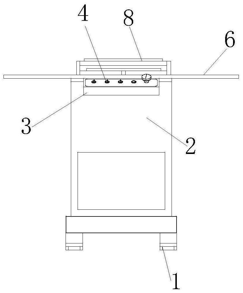
[0033] see figure 1 and figure 2 , the present invention provides a product positioning device for product packaging through improvement, including a support foot 1, a fixed frame 2, a placement plate 6, a chute 7 and a reciprocating conveying mechanism 8, the four corners of the bottom of the support foot 1 and the fixed frame 2 Welding and fixing, the upper right end of the fixed frame 2 is provided with a control panel 3, the front end of the control panel 3 is equipped with a button 4, the reciprocating conveying mechanism 8 is installed and fixed inside the fixed frame 2, the rear end of the fixed frame 2 is fixed with a power supply wire 5, the fixed frame 2 and The bottom of the placement plate 6 is fixedly connected, the left and right sides of the top of the placement plate 6 are oppositely provided with chute 7, the rear end of the fixed frame 2 is fixed with a power lead 5, the fixed frame 2 is fixedly connected with the bottom of the placement plate 6, and the lef...

Embodiment 2

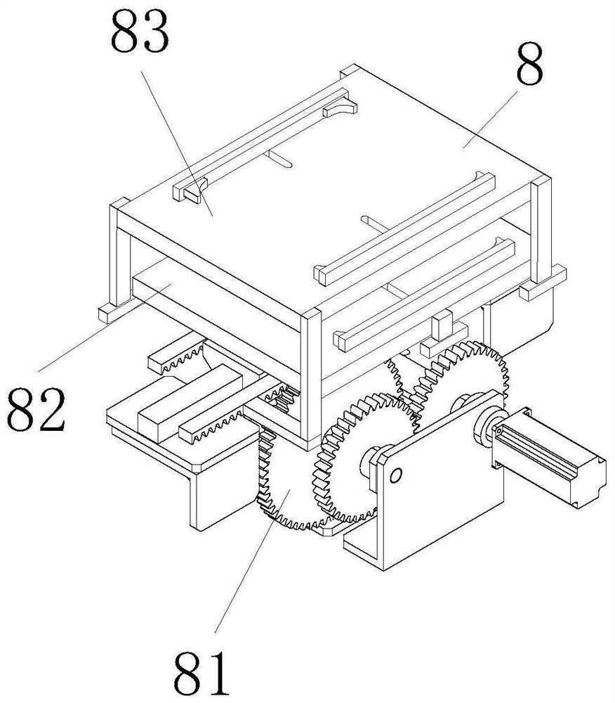
[0041] The present invention provides a product positioning device for product packaging through improvement. The middle part of the moving plate 8256 is provided with a protruding rod 82561, and the protruding rod 82561 is welded and fixed to the bottom of the connecting plate 82591, which is beneficial to fix and support the connecting plate 82591. There are three second guide rods 833, and the second guide rods 833 are respectively located on the right side of the front end of the second horizontal plate 832 and on the left and right sides of the rear end of the second horizontal plate 832, which is beneficial to make the second horizontal plate 832 The role of smooth movement.

[0042] The present invention provides a product positioning device for product packaging through improvement, and its working principle is as follows;

[0043] First, before use, place the product positioning device used for product packaging horizontally, make the support foot 1 fix the device, an...


PUM


Abstract

The invention discloses a product positioning device for product packaging. The device comprises supporting legs, a fixed frame, a placement plate, a sliding groove and a reciprocating conveying mechanism, the supporting legs are fixed to four corners of the bottom of the fixed frame in a welded mode, and a control panel is arranged at the upper right end of the fixed frame. According to the device, through the arrangement that the reciprocating conveying mechanism is arranged inside the fixed frame, and through the forward and reverse rotations of a first large gear and a second large gear, asecond rack and a first rack are driven to move in opposite directions, so that when a first fixed plate is in a processing area, a second fixed plate is located in a product placement area, when thefirst fixed plate is in the product placement area, the second fixed plate is located in the processing area, and the advantages of circulating conveying of products and improving packaging efficiency are achieved.

Description

technical field [0001] The invention relates to the related field of product packaging, in particular to a product positioning device for product packaging. Background technique [0002] Product packaging refers to the general term for the decoration attached to the product by using containers, materials and auxiliary materials according to certain technical methods in order to protect the product, facilitate storage and promote sales during the circulation process of product transportation, storage, and sales. It is conducive to ensuring the safety and product quality of special products, and can well protect the legitimate rights and interests of product warehousers, transporters, sellers and consumers. [0003] When packaging products, it is often necessary to use a product positioning device to position the product. The current positioning device is generally simple in structure, and the product is clamped and fixed by the cylinder. After the product is packaged, it is o...

Claims


Application Information

Patent Timeline
IPC IPC(8): B65B35/56B65B35/16B65B61/28
CPCB65B35/16B65B35/56B65B61/28
Inventor 钟良华
Owner 泉州市高谦机械产品有限公司
Learn More