
Bladeless underwater propulsion system

A propulsion system and submersible technology, applied in ships, special purpose ships, underwater ships, etc., can solve the problems of needing to be replaced regularly, unable to sneak, unable to provide power, etc., to minimize noise and friction loss, reduce disturbance and Vortex, the effect of improving work performance

Active Publication Date: 2020-09-25
JIANGSU UNIV
View PDF10 Cites 1 Cited by
  • Summary
  • Abstract
  • Description
  • Claims
  • Application Information

AI Technical Summary

Problems solved by technology

However, during the actual use of the propeller propeller, the blades are often entangled by aquatic plants and other debris, resulting in malfunctions and loud noises, making it impossible to sneak in turbid waters (containing solid particles such as sand and aquatic plants and other debris); and A vehicle needs to be equipped with multiple sets to maintain the adjustment of the direction of travel. It needs multiple sets of motors or power devices to drive, which is bulky and cumbersome to control.
For some underwater miniature submersibles, energy-saving pump-jet propellers are used to provide power, and four airfoils are used for multi-degree-of-freedom control. Although it has the advantages of simple structure, energy saving and environmental protection, there are also obvious shortcomings and problems: The airfoil wall can only control the direction and cannot provide power; the blades are easily damaged and need to be replaced regularly
Although the magnetic fluid thruster has the advantages of flexible maneuverability, good maneuverability, low vibration and noise, and convenient layout, it has high costs, incomplete technical conditions, and cannot work in freshwater environments.

Method used


Image

  • Bladeless underwater propulsion system
  • Bladeless underwater propulsion system
  • Bladeless underwater propulsion system

Examples


Embodiment Construction

[0027] The present invention will be further described below in conjunction with the accompanying drawings and specific embodiments, but the protection scope of the present invention is not limited thereto.

[0028] In describing the present invention, it is to be understood that the terms "center", "upper", "lower", "front", "rear", "left", "right", "vertical", "horizontal", The orientations or positional relationships indicated by "top", "bottom", "inner", "outer", etc. are based on the orientations or positional relationships shown in the drawings, and are only for the convenience of describing the present invention and simplifying the description, rather than indicating or implying the It should not be construed as limiting the invention that a device or element must have a particular orientation, be constructed, and operate in a particular orientation.

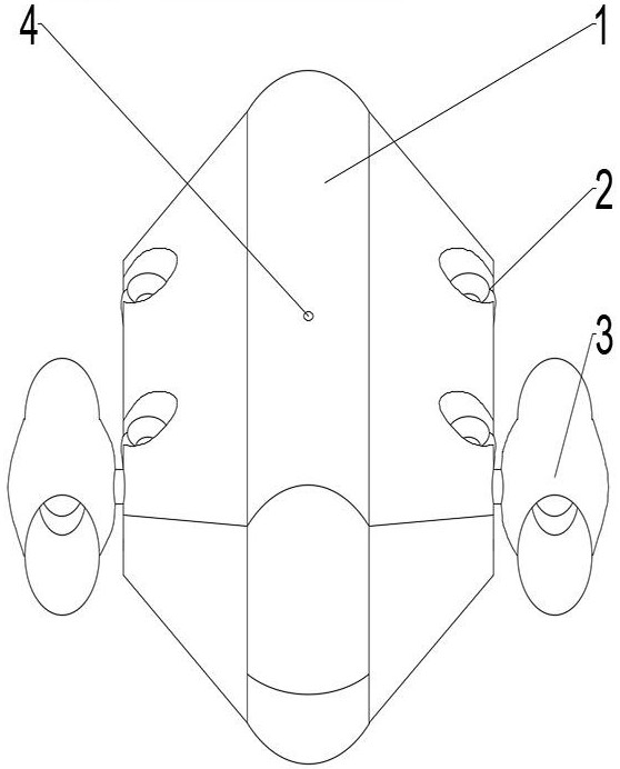
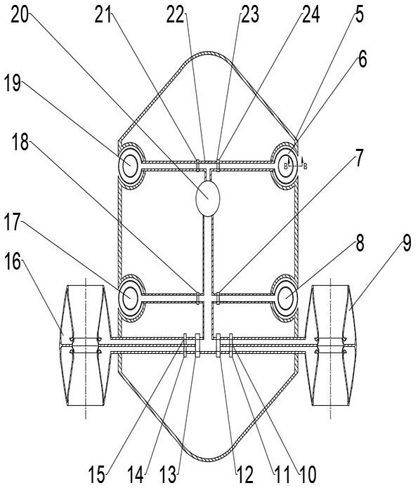
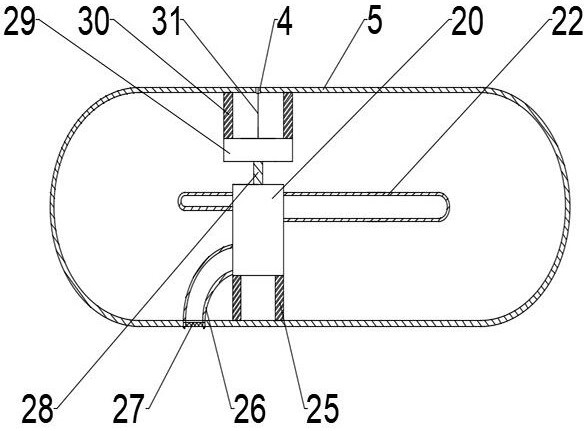
[0029] Such as figure 1 , figure 2 , image 3 and Figure 4 As shown, the bladeless submersible propulsion system ...


PUM

PropertyMeasurementUnit
Widthaaaaaaaaaa

Abstract

The invention provides a bladeless underwater propulsion system. The bladeless underwater propulsion system comprises a main base body, a vertical propeller set and a horizontal propeller set. The main base body comprises a shell, a variable-frequency direct-current permanent magnet motor, a cable connector, supercharging equipment, a water inlet pipeline, a water outlet pipeline and the like. Thevertical propeller set is used for providing power for the bladeless underwater propulsion system to float upwards, and the horizontal propeller set is used for providing power for the bladeless underwater propulsion system to advance, retreat and turn. An electromagnetic valve is arranged on the water outlet pipeline and used for adjusting the size and direction of water flow of outlet pipelinesof all the branches, then the thrust of all the propellers is changed, and therefore the movement functions of floating, diving, advancing, retreating, turning and the like of the bladeless underwater propulsion system are achieved. The bladeless underwater propulsion system can adapt to underwater severe environments, and has the advantages of high compatibility, low noise, high safety coefficient, compact structure, small size, light weight and the like.

Description

technical field [0001] The invention relates to the field of underwater propulsion, and is suitable for use as a power device for unmanned underwater vehicles, in particular to a bladeless submarine propulsion system. Background technique [0002] With the development of my country's science and technology, my country's underwater unmanned submersibles and related technologies are getting better and better, and the functions and application places of the underwater unmanned submersibles made It can not only detect underwater operations in highly dangerous waters, but also replace manual detection of underwater operations in shallow water areas. Some of the more common fields such as marine energy mining, underwater detection of dam gate valves, cleaning of sewer pipes, dredging of water areas, Water environment testing, etc. Therefore, underwater unmanned submersibles are of great significance to our production and life. In the process of research and development of underwate...

Claims


Application Information

Patent Timeline
IPC IPC(8): B63G8/08B63G8/14
CPCB63G8/08B63G8/14B63G2008/002
Inventor 司乔瑞陈猛飞袁建平袁寿其邱宁
Owner JIANGSU UNIV
Learn More