
Wax injection nozzles for precision casting wax pressing and injection equipment

A technology of precision casting and wax injection, which is applied in the direction of casting molding equipment, etc. It can solve the problems of poor surface quality of wax molds, insufficient wax injection process, and blockage of wax injection nozzles, etc., to achieve novel shapes

Inactive Publication Date: 2020-09-25
霍山县忠福机电科技有限公司
View PDF0 Cites 0 Cited by
  • Summary
  • Abstract
  • Description
  • Claims
  • Application Information

AI Technical Summary

Problems solved by technology

[0002] Investment casting and lost wax casting, including wax pressing, wax repairing, tree formation, dipping, melting wax, pouring molten metal and related follow-up processing processes, usually refers to preparing related device shapes from fusible materials, and then remodeling The surface is covered with refractory materials to make a shell, and then the pattern is melted and discharged from the shell to obtain the corresponding mold. After high-temperature roasting, it can be filled with sand and poured. The investment casting process is complicated and not easy to control, and the existing wax The material has strict standards in the filling process. When the wax slurry is injected into the mold from the sprue, because the sprue is usually on the top or side of the mold, this will cause the injected wax slurry to splash and make the surface quality of the wax mold poor. The wax machine assembly line injects wax into the mold. In this way, the wax in the wax injection nozzle will solidify quickly at a certain interval, and the wax injection nozzle is prone to be blocked by wax, resulting in insufficient wax injection process and reduced wax injection efficiency.

Method used


Image

  • Wax injection nozzles for precision casting wax pressing and injection equipment
  • Wax injection nozzles for precision casting wax pressing and injection equipment
  • Wax injection nozzles for precision casting wax pressing and injection equipment

Examples


Embodiment Construction

[0023] In order to make those skilled in the art better understand the technical scheme of the present invention, the present invention will be further described below in conjunction with embodiment:

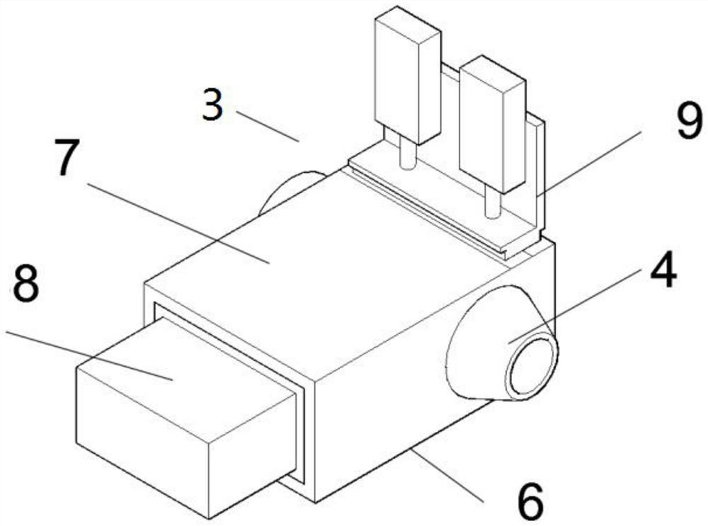
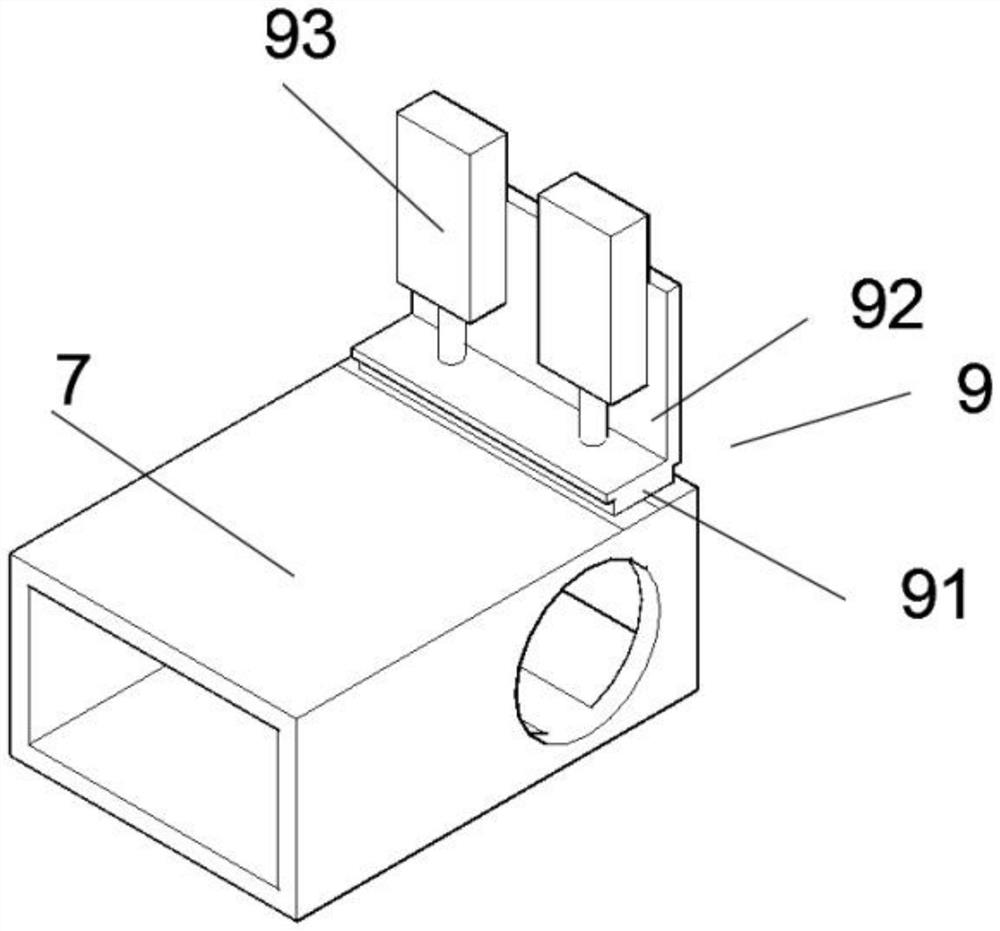
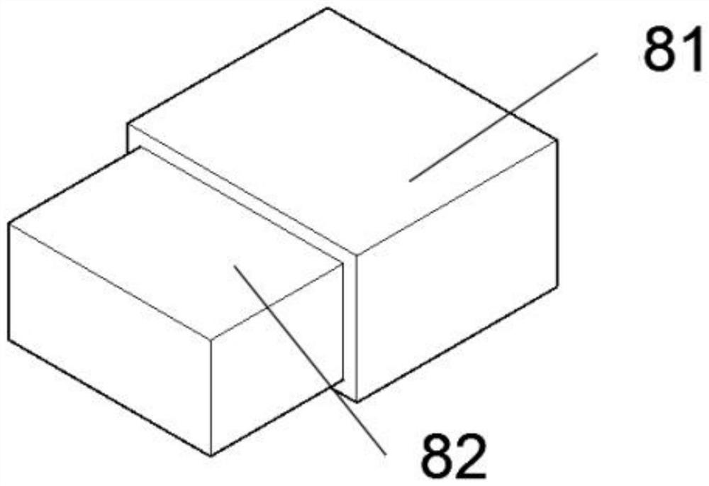
[0024] For specific embodiments, refer to the accompanying drawings, a wax injection nozzle for precision casting wax injection equipment, including a fixed telescopic piece 1, which is arranged on a rotary table 2 on the outer circumference of the bottom of the column, and the fixed telescopic piece 1 The telescoping ends are movably connected with a wax injection nozzle 3, the wax injection nozzle 3 includes a nozzle head 4, the nozzle head 4 is connected with the wax injection body 5, and the outer circumference of the wax injection body 5 is connected with a feeding device 6, so The feeding device 6 includes a feeding member 7 arranged outside the wax injection body 5 , one end of the feeding member 7 is provided with a feeding pushing device 8 , and the other end of the feed...


PUM


Abstract

The invention discloses wax injection nozzles for precision casting wax pressing and injecting equipment. The wax injection nozzle comprises fixed telescopic parts, wherein the fixed telescopic partsare arranged on a rotating table on the outer circumference of the bottom of a stand column, and the telescopic ends of the fixed telescopic parts are movably connected with wax injection nozzle bodies; wax injection nozzle bodies comprise nozzle heads, and the nozzle heads are connected with wax injection bodies; and the outer circumferences of the wax injection bodies are connected with feedingdevices, the feeding devices comprise feeding pieces arranged outside the wax injection bodies, feeding pushing devices are arranged at one ends of the feeding pieces, and blocking devices are arranged at the other ends of the feeding pieces. The wax injection nozzles for the precision casting wax pressing and injecting equipment is novel in shape, wax injection pipelines arranged in stacking frames can be pushed into hollow cylinders of the wax injection bodies through the feeding pushing devices, and replacement of the wax injection pipelines is achieved so that the problem that the wax injection nozzle bodies are blocked by wax can be effectively solved.

Description

technical field [0001] The invention relates to the technical field of precision casting equipment, in particular to a wax injection nozzle of precision casting wax injection equipment. Background technique [0002] Investment casting and lost wax casting include pressing wax, repairing wax, forming trees, dipping slurry, melting wax, pouring molten metal and related subsequent treatment processes. The surface is covered with refractory material to make a shell, and then the pattern is melted and discharged from the shell to obtain the corresponding mold. After high-temperature roasting, it can be filled with sand and poured. The investment casting process is complicated and not easy to control, and the existing wax The material has strict standards in the filling process. When the wax slurry is injected into the mold from the sprue, because the sprue is generally on the top or side of the mold, this will cause the injected wax slurry to splash, making the surface quality of...

Claims


Application Information

Patent Timeline
Patent Type & Authority Applications(China)
IPC IPC(8): B22C7/02
CPCB22C7/02
Inventor 杨德军李雪韩锐孙书群刘坤张友龙安建国汪玉杨青
Owner 霍山县忠福机电科技有限公司
Learn More