Method for embossing a component

A technology of parts and parts, applied in the direction of household components, applications, cold-pressed connections, etc., can solve problems such as dimensions that are not conducive to reliable welding, welding gaps are not constant, etc.

Active Publication Date: 2020-09-25
MAHLE INT GMBH
View PDF6 Cites 0 Cited by
  • Summary
  • Abstract
  • Description
  • Claims
  • Application Information

AI Technical Summary

Problems solved by technology

[0003] A disadvantage of the known embossing method is that due to the embossing pressure, the material part of the sheet metal part flows transversely to the direction of action of the embossing pressure during embossing of the groove
Thus, the groove forms side walls oriented obliquely to one another, so that the welding gap between the groove and the second part is not constant and can have dimensions that are not conducive to reliable welding

Method used


Image

  • Method for embossing a component
  • Method for embossing a component
  • Method for embossing a component

Examples


Embodiment Construction

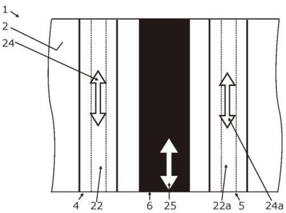
[0055] figure 1 A first component 1 with embossing according to the invention is shown, wherein the first component has at least a first surface portion 2 and a second surface portion 3 . Prior to the embossing process according to the invention, the first component 1 has a first surface portion 2 which can be formed analogously to the second surface portion 3 shown. The first surface portion 2 and the second surface portion 3 are positioned opposite each other and are spaced apart from each other. The distance between the first surface portion 2 and the second surface portion 3 outside the embossed area or groove defines the wall thickness 17 .

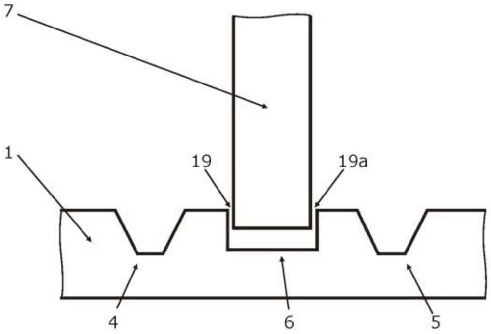
[0056] With the method of the invention for embossing a component, a first support groove 4 , a second support groove 5 and a functional groove 6 are embossed into the first component 1 at least partially at the first surface portion 2 .

[0057] The first support groove 4 and the second support groove 5 are arranged at least parti...


PUM

PropertyMeasurementUnit
widthaaaaaaaaaa

Abstract

The present disclosure concerns a method for embossing a component, and a method for connecting a component to a second component. The invention also relates to a device having such a component. The invention is based on the overall concept that at least one support groove is inserted and / or introduced into the peripheral region of a functional groove in order to reduce the flow of the material part of the component transversely to the imprint pressure application direction.

Description

technical field [0001] The invention relates to a method for embossed components and a method for materially connecting an embossed first part with a second part. The invention also relates to a device having at least one embossing element. Background technique [0002] It is known from the prior art that the sheet metal part can have embossed grooves into which the second part is inserted. The sheet metal part is then welded to the second part, wherein flux is introduced into the welding gap between the embossed groove of the sheet metal part and the second part. A weldable design requires a small weld gap to ensure adequate capillary action and a reliable weld. [0003] A disadvantage of the known embossing method is that, due to the embossing pressure, the material part of the sheet metal part flows transversely to the direction of action of the embossing pressure during the embossing of the groove. Thus, the groove forms side walls that are oriented obliquely to one a...

Claims


Application Information

Patent Timeline
Patent Type & Authority Applications(China)
IPC IPC(8): B21D17/02B23K20/02F16B11/00
CPCB21D17/02B23K20/026F16B11/004F16B11/006B29C59/007B29C59/02B29C59/022B29L2031/18B29C59/005
Inventor 克劳斯·哈斯登托伊费尔斯蒂芬·席尔丹尼尔·施莱歇尔
Owner MAHLE INT GMBH
Why Eureka
Try Eureka