Direct motion guide device and assembly method thereof
A technology of guiding devices and guide rails, which is applied in the direction of linear motion bearings, shafts, bearings, bearings, etc., which can solve the problems of rolling motion damage of rolling elements and reduced sliding performance of sliding elements, and achieve low cost and improved sealing.
- Summary
- Abstract
- Description
- Claims
- Application Information
AI Technical Summary
Problems solved by technology
Method used
Image


Examples
no. 1 approach
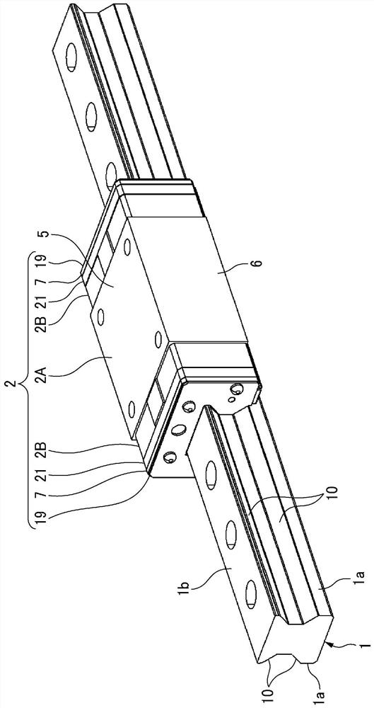
[0140] Such as figure 1 As shown, the linear guide device of the first embodiment includes a guide rail 1 extending in the axial direction and a slider 2 assembled so as to straddle the guide rail 1 and be relatively movable in the axial direction of the guide rail 1 .
[0141] On the left and right side surfaces 1 a , 1 a of the guide rail 1 , two upper and lower guide rail side track surfaces 10 are formed along the axial direction of the guide rail 1 .
[0142] Such as figure 1 and figure 2 As shown, the slider 2 includes a slider main body 2A and slider end surface members detachably attached to both ends in the axial direction. Examples of the slider end surface member include the end cover 2B, the lubricating unit 21, the side seal 7, the mounting plate 19, and the like. As other sliding body end surface members, various dustproof members and the like can be mentioned.
[0143] The slider main body 2A has an upper portion 5 along the upper surface 1b of the guide ...
no. 2 approach
[0198] Next, refer to Figure 15 as well as Figure 16The lower seal 330 according to the second embodiment will be described. In the above-mentioned embodiment, the sealing cover 32 is formed by stamping a sheet metal, but the sealing cover 332 of the present embodiment is as Figure 15 As shown, it is formed by resin injection molding.
[0199] In addition, in this seal cover 332 , the fitting protrusion 32 d does not have a space SP for receiving the head of the screw 33 , and the head of the screw 33 protrudes downward from the bottom wall 32 a of the seal cover 32 . In this case, the opening 32e formed in the fitting convex portion 32d is constituted by a through hole having the same inner diameter in the thickness direction of the lower seal 330, and the outer peripheral surface of the fitting convex portion 32d has a tapered shape as in the first embodiment.
[0200] Such as Figure 16 As shown, a tapered fitting hole 31c is formed in the sealing member 331 in accor...
no. 3 approach
[0203] Next, refer to Figure 17 (a) and Figure 17 (b) describes the lower seal 430 according to the third embodiment. Such as Figure 17 As shown in (a), the sealing cap 432 of the present embodiment has the side wall portion 32 b and the end wall portion 32 c removed from the sealing cap 32 of the first embodiment. Thereby, the manufacturing cost of the sealing cover 432 can be suppressed. The sealing member 31 is the same as in the above-mentioned embodiment.
[0204] In this embodiment, when the seal member 31 is assembled to the seal cover 432, the inside tapered surface 31d contacts the outside tapered surface 32f, and the fitting hole 31c and the fitting convex portion 32d are fitted and positioned relative to each other.
[0205] Other structures and functions are the same as those of the above-mentioned first embodiment.
PUM
 Abstract
Description
Claims
Application Information
 - Generate Ideas
- Intellectual Property
- Life Sciences
- Materials
- Tech Scout
- Unparalleled Data Quality
- Higher Quality Content
- 60% Fewer Hallucinations
Browse by: Latest US Patents, China's latest patents, Technical Efficacy Thesaurus, Application Domain, Technology Topic, Popular Technical Reports.
© 2025 PatSnap. All rights reserved.Legal|Privacy policy|Modern Slavery Act Transparency Statement|Sitemap|About US| Contact US: help@patsnap.com