


Quick Research
Generate reliable direction feasibility study reports for your R&D in just a few steps.

Technical Q&A
Discover and master advanced knowledge NOW. Basics, ideas, possibilities, all at once.

Find Solutions
As an expert in R&D theories, this can generate solutions to your technical problems instantly.

Evaluate Feasibility
Analyze your overall solution with one click, know your potential R&D risks in advance.

Monitor Landscape
Get weekly tech updates, stay abreast of the latest tech innovations and key insights.
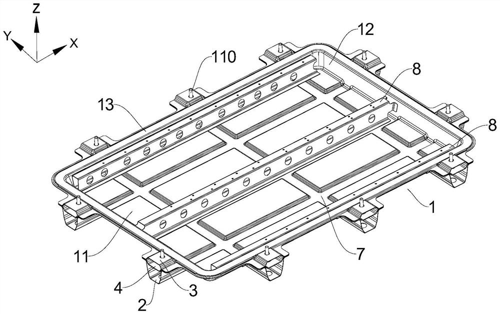
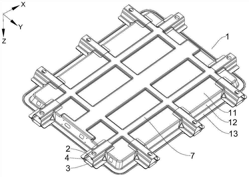
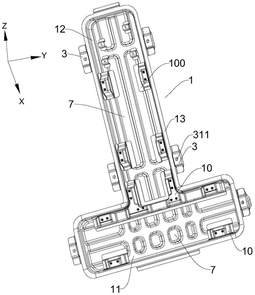
Battery trays, traction battery packs and vehicles
A battery tray and tray technology, which is applied in the field of vehicles, can solve problems such as unfavorable protection of single batteries, low structural strength of the mounting part, deformation and damage of the mounting part, etc., so as to facilitate the transmission and dispersion of force, not easily deform, and avoid deformation and damage. Effect
- Summary
- Abstract
- Description
- Claims
- Application Information
AI Technical Summary
Problems solved by technology
Method used
Image

Examples
Embodiment Construction
[0054]Specific embodiments of the present disclosure will be described in detail below in conjunction with the accompanying drawings. It should be understood that the specific embodiments described here are only used to illustrate and explain the present disclosure, and are not intended to limit the present disclosure.
[0055] In this disclosure, unless stated otherwise, the used orientation words such as "up and down" are generally relative to the normal driving state of the vehicle, specifically, towards the direction of the roof of the vehicle when the vehicle is running normally. is "up", and the direction toward the vehicle chassis is "down"; in addition, "vertical" refers to the up and down direction of the vehicle, that is, the Z direction shown in the drawings, and "lateral" refers to the direction perpendicular to the vertical , that is, the front-rear and left-right directions of the vehicle, the X and Y directions shown in the drawings; in addition, "inside and out...
PUM
| Property | Measurement | Unit |
|---|---|---|
| height | aaaaa | aaaaa |
| yield strength | aaaaa | aaaaa |
| tensile strength | aaaaa | aaaaa |
Abstract
Description
Claims
Application Information
 - R&D Engineer
- R&D Manager
- IP Professional
- Industry Leading Data Capabilities
- Powerful AI technology
- Patent DNA Extraction
Browse by: Latest US Patents, China's latest patents, Technical Efficacy Thesaurus, Application Domain, Technology Topic, Popular Technical Reports.
© 2024 PatSnap. All rights reserved.Legal|Privacy policy|Modern Slavery Act Transparency Statement|Sitemap|About US| Contact US: help@patsnap.com