Weak capacitance change measuring circuit
A weak capacitance and measurement circuit technology, applied in capacitance measurement, measurement of electrical variables, measurement of resistance/reactance/impedance, etc., can solve the problems of complex system and reduced measurement system accuracy.
- Summary
- Abstract
- Description
- Claims
- Application Information
AI Technical Summary
Problems solved by technology
Method used
Image
Examples
Embodiment 1
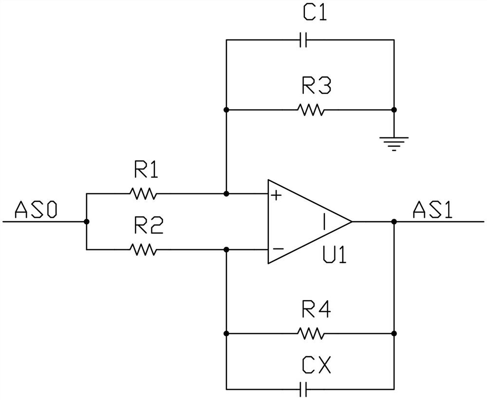
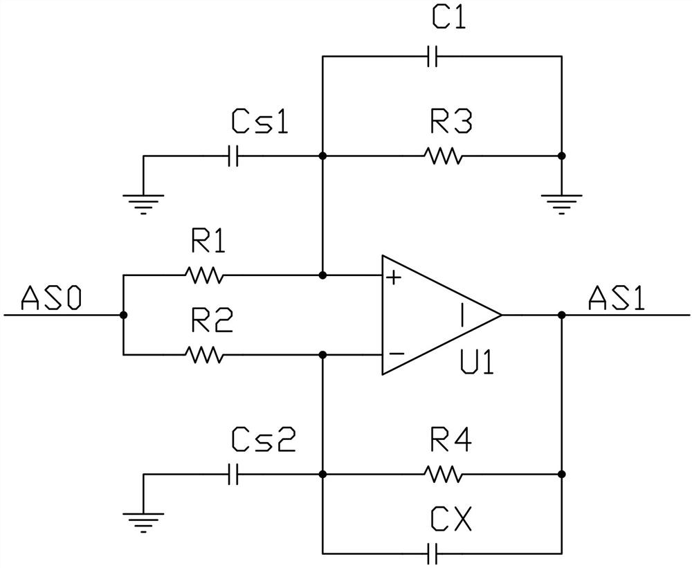
[0037] figure 1 It shows the circuit principle block diagram of the first embodiment of the present invention. The present invention provides a weak capacitance change measurement circuit, including: CV conversion circuit, amplification circuit, analog multiplier, low-pass filter and phase shifting circuit. After the sine wave excitation signal is input to the CV conversion circuit, the CV conversion circuit converts the relative change rate of the capacitance value of the capacitive sensor into the amplitude change of a weak sinusoidal signal; the weak sinusoidal signal is amplified by the amplifier circuit; the amplitude of the output signal of the amplifier circuit It is resolved by the amplitude demodulation circuit composed of an analog multiplier and a low-pass filter, and the DC useful signal proportional to the relative change rate of the equivalent capacitance of the sensor is output through the low-pass filter; the phase shifter changes the reference signal of the amp...
Embodiment 2
[0069]In order to reduce costs, the reference signal can be replaced by a square wave, and the analog multiplier can be replaced by an electronic switching multiplier. Use the reference signal to control the electronic switch, so that the output of the CV conversion circuit is alternately multiplied by a coefficient with equal absolute value but opposite sign. The result of the multiplication contains a series of AC signals and a useful DC signal. The voltage value of the useful DC signal is proportional to the amplitude of the CV conversion circuit, and also proportional to the cosine value of the phase difference between the reference square wave and the output signal of the CV conversion circuit. The function of the phase shifting circuit is the same as that described above. In order to save a signal source, the reference square wave signal can be converted from a sinusoidal excitation signal through a zero-crossing comparator. The block diagram of the circuit is as Fig...
PUM
 Abstract
Description
Claims
Application Information
 - Generate Ideas
- Intellectual Property
- Life Sciences
- Materials
- Tech Scout
- Unparalleled Data Quality
- Higher Quality Content
- 60% Fewer Hallucinations
Browse by: Latest US Patents, China's latest patents, Technical Efficacy Thesaurus, Application Domain, Technology Topic, Popular Technical Reports.
© 2025 PatSnap. All rights reserved.Legal|Privacy policy|Modern Slavery Act Transparency Statement|Sitemap|About US| Contact US: help@patsnap.com


