
Power grid resonance point detection device and method

A detection method and resonance point technology are applied in the field of power grid resonance point detection devices, which can solve the problems of unsatisfactory field application effect, poor real-time performance, complicated operation, etc., and achieve real-time online detection problems, simple device structure and high detection accuracy Effect

Inactive Publication Date: 2020-09-22
ELECTRIC POWER RESEARCH INSTITUTE, CHINA SOUTHERN POWER GRID CO LTD +1
View PDF3 Cites 4 Cited by
  • Summary
  • Abstract
  • Description
  • Claims
  • Application Information

AI Technical Summary

Problems solved by technology

[0003] Therefore, in order to achieve the purpose of resonance suppression, the compensation equipment must determine the resonance frequency of the power grid in advance before working. The existing resonance point detection scheme is complicated to operate, has poor real-time performance, and the field application effect is not ideal. Therefore, research on the real-time online detection scheme of the grid resonance point , is of great significance

Method used


Image

  • Power grid resonance point detection device and method
  • Power grid resonance point detection device and method
  • Power grid resonance point detection device and method

Examples


Embodiment Construction

[0045] In order to enable those skilled in the art to better understand the solution of the present application, the technical solution in the embodiment of the application will be clearly and completely described below in conjunction with the accompanying drawings in the embodiment of the application. Obviously, the described embodiment is only It is a part of the embodiments of this application, not all of them. Based on the embodiments in this application, all other embodiments obtained by persons of ordinary skill in the art without making creative efforts belong to the scope of protection of this application.

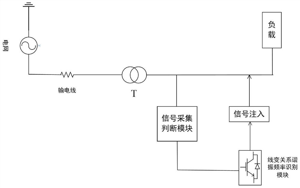
[0046] figure 1 It is a structural connection diagram of an embodiment of a power grid resonance point detection device, such as figure 1 It includes: the line-change relationship resonant frequency identification module and the signal acquisition and judgment module connected between the reactive power compensation capacitor and the load of the power grid, the li...


PUM


Abstract

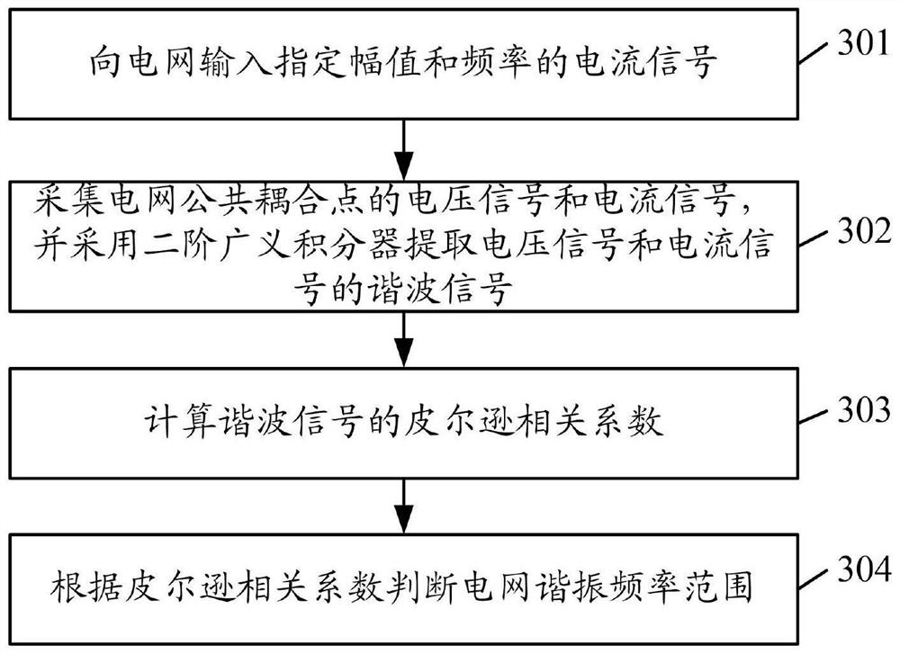
The invention discloses a power grid resonance point detection device and method. The device comprises a line-change relation resonance frequency recognition module and a signal acquisition and judgment module which are connected between a power grid reactive compensation capacitor and a load, wherein the line-change relation resonance frequency recognition module is connected with the signal acquisition and judgment module, the line-change relation resonant frequency recognition module is used for injecting a current signal with specified amplitude and frequency into a power grid, the signalacquisition and judgment module is used for acquiring voltage and current signals of a power grid common coupling point and judging the resonant frequency range of the power grid according to the voltage and current signals. The device is simple in structure, real-time online detection of the resonant frequency of the power grid can be realized, and the resonant frequency of the power grid can bedetected only by acquiring the voltage and current signals of the common coupling point outputted by the line change relation identification device.

Description

technical field [0001] The present application relates to the technical field of resonance detection, in particular to a power grid resonance point detection device and method. Background technique [0002] The power quality problem of power grid has been widely concerned. Due to the complex load conditions on the low-voltage side, the application of various nonlinear loads will cause the power quality and power factor of the power grid to decline. Shunt capacitors and active power filters are often used to compensate for the influence of harmonics and reactive currents in the power grid. When the equipment compensates for harmonics, it is equivalent to a background harmonic source near the resonance point of the power grid, which is likely to cause resonance of the power grid. Resonance will cause severe distortion of the harmonic current or voltage of the power grid, and the resulting resonance current will cause equipment damage and even casualties. [0003] Therefore, ...

Claims


Application Information

Patent Timeline
Patent Type & Authority Applications(China)
IPC IPC(8): G01R23/02
CPCG01R23/02
Inventor 金鑫徐兵肖勇杨劲锋
Owner ELECTRIC POWER RESEARCH INSTITUTE, CHINA SOUTHERN POWER GRID CO LTD
Learn More