Dehydrator anti-meandering and tension protection device and method

A protection device and anti-deviation technology, which is applied in the direction of conveyor control devices, transportation and packaging, conveyors, etc., can solve problems such as unreasonable installation, protection switches are easily damaged by moisture, and short-circuited contacts, etc., to achieve extended Long service life, convenient daily maintenance, and the effect of preventing the switch from refusing to move

Pending Publication Date: 2020-09-22
DATANG HUAYIN ELECTRIC POWER
View PDF0 Cites 0 Cited by
  • Summary
  • Abstract
  • Description
  • Claims
  • Application Information

AI Technical Summary

Problems solved by technology

[0003] 1. Water ingress in the switch causes a short circuit of the contact, and a wrong signal is sent to cause the dehydrator to trip;
[0004] 2. The installation is unreasonable, and the protection switch is easily damaged by moisture;
[0005] 3. The deviation switch cannot be triggered when the filter cloth is turned over when it deviates;
[0006] 6. The tension switch and the hanging roller are in hard contact, and the switch is often damaged by impact when tension occurs;
[0007] 5. The tension switch adopts a normally open contact, and when the suspension roller rises instantaneously in the case of tension, sometimes it will directly fall out of the range of the travel switch, but the tension switch cannot maintain the instantaneous trigger condition, and sometimes the protection does not start to operate. Disappeared

Method used


Image

  • Dehydrator anti-meandering and tension protection device and method
  • Dehydrator anti-meandering and tension protection device and method
  • Dehydrator anti-meandering and tension protection device and method

Examples


Embodiment Construction

[0028] In order to make the purpose, technical solution and advantages of the present invention clearer, the technical solution of the present invention will be described in detail below. Apparently, the described embodiments are only some of the embodiments of the present invention, but not all of them. Based on the embodiments of the present invention, all other implementations obtained by persons of ordinary skill in the art without making creative efforts fall within the protection scope of the present invention.

[0029] The present invention will be further described below in conjunction with the accompanying drawings, but the protection scope of the present invention is not limited to the following description.

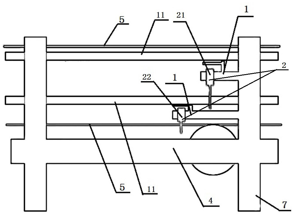
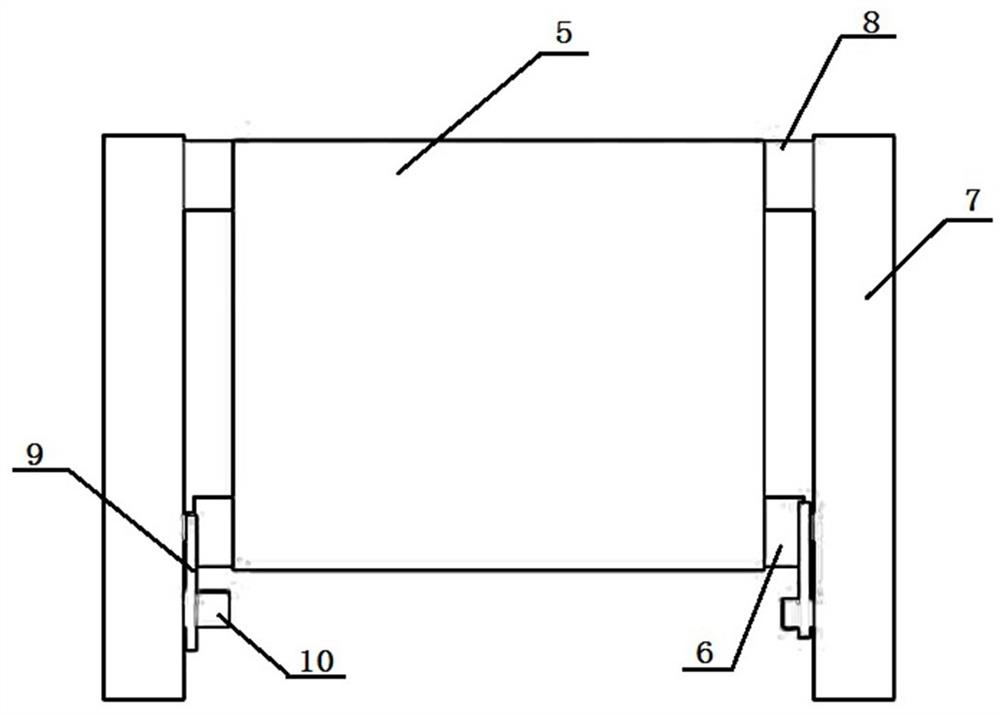
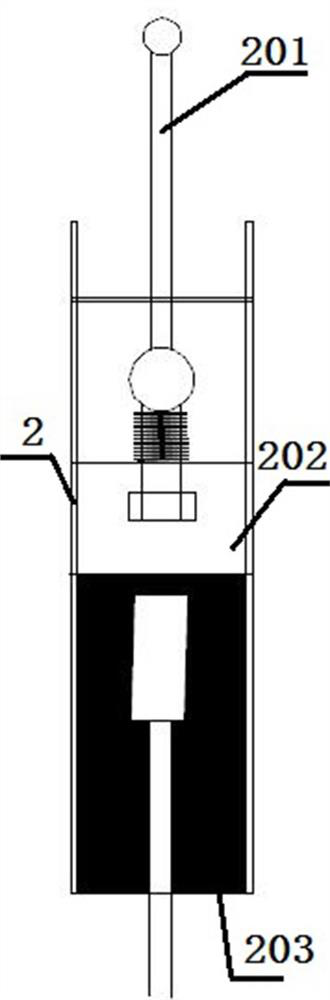
[0030] Such as Figure 1-3 Shown:

[0031] The invention provides a dehydration machine anti-deviation and tension protection device, comprising a filter cloth 5, a hanging roller 6, a support roller 4, a fixed roller 8, a belt 11 and a frame 7, and the filte...


PUM


Abstract

The invention provides a dehydrator anti-meandering and tension protection device and method and relates to the field of gypsum dehydration equipment. The device comprises a dehydrator, two groups ofcrank arm switches, a group of inductive switches and a control system. The inductive switches are all mounted on a rack. Hanging rollers are connected with the inductive switches through metal wirescorrespondingly. The device further comprises water shields fixed to the rack. The water shields correspond to the crank arm switches in a one-to-one correspondence mode. The two groups of crank arm switches comprise the first group of crank arm switches used for preventing meandering of a belt and the second group of crank arm switches used for preventing meandering of filter cloth; and the groups of crank arm switches are fixed into the water shields on the two sides of the belt and the filter cloth correspondingly. Glue filling areas are arranged in the crank arm switches correspondingly. Both the crank arm switches and the inductive switches are connected with the control system. According to the dehydrator anti-meandering and tension protection device and method, by shifting the crankarm switches and changing the mounting mode, the models of the inductive switches and the ways to obtain signals, the problems of switch operation failures, malfunction and damage are solved, in addition, the waterproofness and corrosion resistance of the switches are improved, and accordingly, the service lives of the switches are prolonged.

Description

technical field [0001] The invention relates to the field of gypsum dehydration equipment, in particular to an anti-deviation and tension protection device for a dehydrator and a use method. Background technique [0002] The desulfurization system includes a vacuum belt dehydrator, which is used for gypsum dehydration. Due to the high humidity on site, the switch is severely corroded, which may easily cause the switch to refuse to operate and malfunction; the filter cloth cannot be well protected, which affects the safe and stable operation of the dehydrator. . The problems existing in the existing dehydrator have the following points: [0003] 1. Water ingress in the switch causes a short circuit of the contact, and a wrong signal is sent to cause the dehydrator to trip; [0004] 2. The installation is unreasonable, and the protection switch is easily damaged by moisture; [0005] 3. The deviation switch cannot be triggered when the filter cloth is turned over when it de...

Claims


Application Information

Patent Timeline
Patent Type & Authority Applications(China)
IPC IPC(8): B65G43/02B65G43/08
CPCB65G43/02B65G43/08B65G2203/0283
Inventor 颜盛肖继庭董万斌刘俊李慧刘凯
Owner DATANG HUAYIN ELECTRIC POWER
Why Eureka
Try Eureka