


Quick Research
Generate reliable direction feasibility study reports for your R&D in just a few steps.

Technical Q&A
Discover and master advanced knowledge NOW. Basics, ideas, possibilities, all at once.

Find Solutions
As an expert in R&D theories, this can generate solutions to your technical problems instantly.

Evaluate Feasibility
Analyze your overall solution with one click, know your potential R&D risks in advance.

Monitor Landscape
Get weekly tech updates, stay abreast of the latest tech innovations and key insights.
A fixed table for processing circular mechanical parts
A technology of mechanical parts and fixing table, applied in the field of mechanical parts, can solve the problems of inconvenience and low efficiency, and achieve the effect of improving production efficiency, convenient use and improving convenience
- Summary
- Abstract
- Description
- Claims
- Application Information
AI Technical Summary
Problems solved by technology
Method used
Image

Examples
Embodiment 1
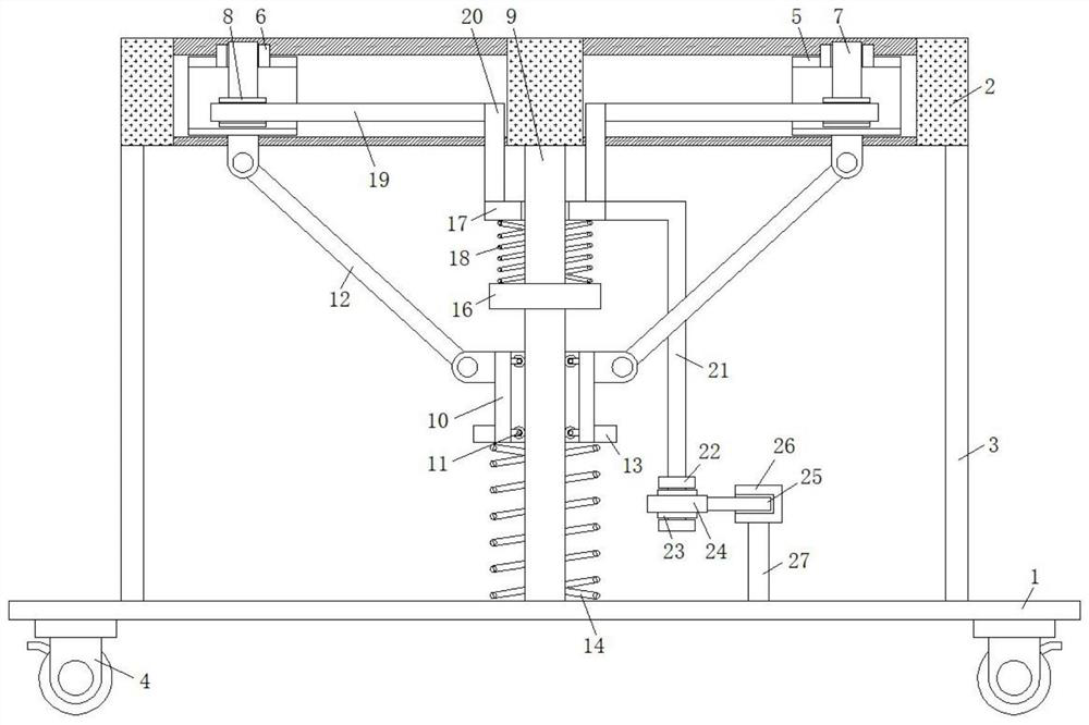
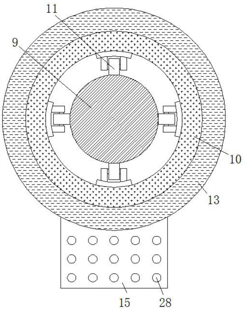
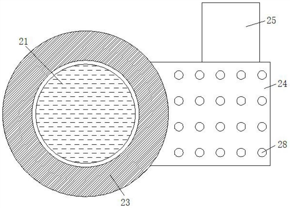
[0024] refer to Figure 1-4 , a fixed platform for processing circular mechanical parts, including a base plate 1, a workbench 2 is arranged vertically above the base plate 1, a support rod 3 is arranged between the bottom side of the workbench 2 and the base plate 1, and the workbench 2 is set There are several divergent sliding chambers, and the bottom and top of the sliding chambers are provided with sliding holes, the sliding chamber is slidably connected with a horizontal cylinder 5, and the top of the horizontal cylinder 5 is provided with a top hole and is fixedly connected with a vertical cylinder 6. The vertical cylinder 6 is slidingly connected with a clamping rod 7, the bottom end of the clamping rod 7 extends into the horizontal cylinder 5 and is fixedly connected with a sleeve 8, and the middle part of the bottom side of the workbench 2 is fixedly connected with a central axis rod 9, and the central axis rod 9 The outer sliding sleeve of the rod body is provided w...
Embodiment 2
[0027] Such as Figure 1-4 As shown, this embodiment is basically the same as Embodiment 1. Preferably, the two ends of the linkage rod 12 are rotatably hinged to the bottom side of the horizontal cylinder 5 and the top outer wall of the sliding sleeve 10 respectively.
[0028] In this embodiment, through the arrangement of the linkage rod 12 , the vertical movement of the sliding sleeve 10 drives the horizontal movement of the horizontal cylinder 5 .
Embodiment 3
[0030] Such as Figure 1-4 As shown, this embodiment is basically the same as Embodiment 1. Preferably, the first spring 14 and the second spring 18 are sleeved on the outer side of the shaft rod 9 .
[0031] In the present embodiment, move on the vertical direction and the horizontal direction of the clip bar 7 realized by stepping down on pedal one 15 and pedal two 24 through the resilience of spring one 14, spring two 18 and people, and then complete the circle The location of shape parts and the accommodation of clamp bar 7.
PUM
 Abstract
Description
Claims
Application Information
 - R&D Engineer
- R&D Manager
- IP Professional
- Industry Leading Data Capabilities
- Powerful AI technology
- Patent DNA Extraction
Browse by: Latest US Patents, China's latest patents, Technical Efficacy Thesaurus, Application Domain, Technology Topic, Popular Technical Reports.
© 2024 PatSnap. All rights reserved.Legal|Privacy policy|Modern Slavery Act Transparency Statement|Sitemap|About US| Contact US: help@patsnap.com