
Eight-station crankcase stator combination machining device

A combined processing and box stator technology, applied in metal processing equipment, metal processing, metal processing mechanical parts, etc., can solve the problems of reduced workpiece processing accuracy, accumulated positioning error, low production efficiency, etc., to reduce performance changes and deformation, The effect of improving the service life and high processing efficiency

Pending Publication Date: 2020-09-18
HUANGSHI HUADAN MACHINE MFG
View PDF0 Cites 5 Cited by
  • Summary
  • Abstract
  • Description
  • Claims
  • Application Information

AI Technical Summary

Problems solved by technology

[0002] The machining of the crankcase stator needs to complete the following processes in sequence, namely: countersinking stator feet, axle outer circle φ19.5X17.5 and tool inspection φ110X30, drilling counterbore, drilling bottom hole, tapping, axle outer circle φ18X16, if it is used Ordinary machine tool processing requires seven processes to complete, at least milling machines, lathes, drilling machines, and tapping are required, and every time a process or a machine tool is changed, the workpiece needs to be processed on a machine tool. Disassemble and then transfer to another machine tool for clamping and positioning. Every time the workpiece is clamped and positioned, cumulative positioning errors will occur, resulting in reduced machining accuracy of the workpiece and high scrap rate. Processing of one workpiece, low production efficiency

Method used


Image

  • Eight-station crankcase stator combination machining device
  • Eight-station crankcase stator combination machining device
  • Eight-station crankcase stator combination machining device

Examples


Embodiment Construction

[0030] In order to make the object, technical solution and advantages of the present invention clearer, the present invention will be further described in detail below in conjunction with the accompanying drawings and embodiments. It should be understood that the specific embodiments described here are only used to explain the present invention, not to limit the present invention. In addition, the technical features involved in the various embodiments of the present invention described below can be combined with each other as long as they do not constitute a conflict with each other.

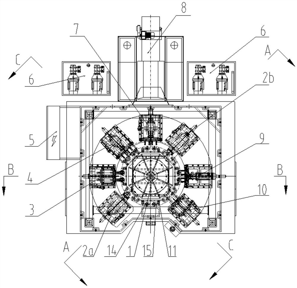
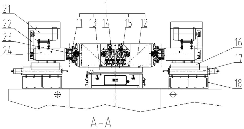
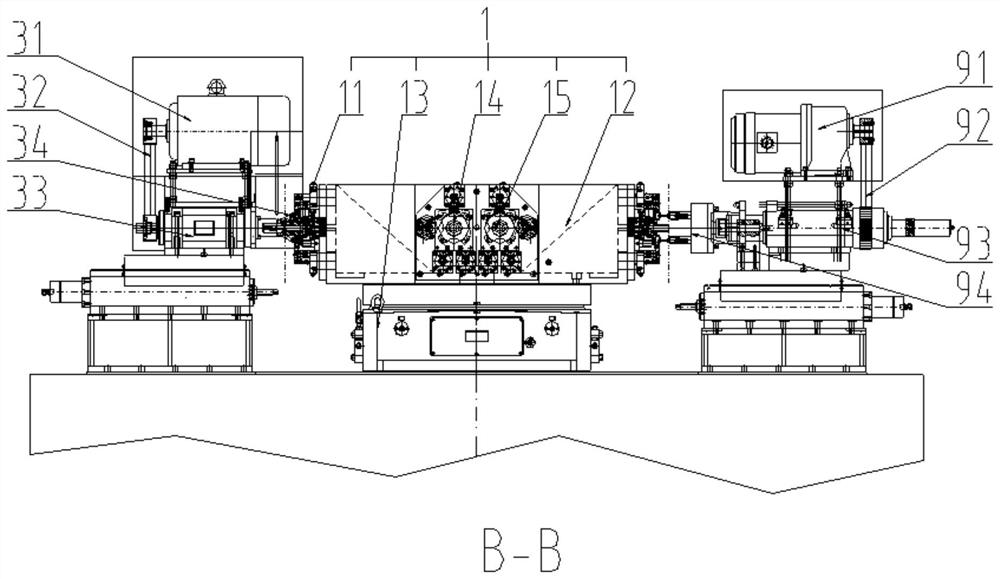
[0031] like figure 1 and figure 2As shown, an eight-station crankcase stator combined processing equipment of the present invention includes an eight-station turntable mechanism 1 fixed on the base, wherein the eight-station turntable mechanism 1 and the base can be connected by welding, bolts, etc. fixed. The eight-station turntable mechanism 1 includes a revolving frame 13 fixed on the bas...


PUM


Abstract

The invention discloses an eight-station crankcase stator combination machining device. The eight-station crankcase stator combination machining device comprises an eight-station rotating disc mechanism, crankcase stator combination machining mechanisms, moving sliding table mechanisms, a cooling mechanism and a control mechanism. The eight-station rotating disc mechanism comprises a rotating frame and a rotating disc arranged on the rotating frame. The rotating disc is rotationally connected with the rotating frame. Workpiece tools are arranged on the rotating disc in the circumferential direction in an array manner. The workpiece tools are used for fixing workpieces. The crankcase stator combination machining mechanisms are arranged in the circumferential direction of the rotating disc in an array manner. The moving sliding table mechanisms are arranged at the bottoms of the crankcase stator combination machining mechanisms and used for driving the crankcase stator combination machining mechanisms to move in the radial direction of the rotating disc. The cooling mechanism is used for cooling the crankcase stator combination machining mechanisms and the workpieces. By the adoptionof the eight-station crankcase stator combination machining device, simultaneously continuous machining of multiple workpieces and multiple processes can be achieved, and the machining efficiency andprecision are high.

Description

technical field [0001] The invention belongs to the technical field of processing machine tools, and more specifically relates to an eight-station crankcase stator combined processing equipment. Background technique [0002] The machining of the crankcase stator needs to complete the following processes in sequence, namely: countersinking stator feet, axle outer circle φ19.5X17.5 and tool inspection φ110X30, drilling counterbore, drilling bottom hole, tapping, axle outer circle φ18X16, if it is used Ordinary machine tool processing requires seven processes to complete, at least milling machines, lathes, drilling machines, and tapping are required, and every time a process or a machine tool is changed, the workpiece needs to be processed on a machine tool. Disassemble and then transfer to another machine tool for clamping and positioning. Every time the workpiece is clamped and positioned, cumulative positioning errors will occur, resulting in reduced machining accuracy of th...

Claims


Application Information

Patent Timeline
Patent Type & Authority Applications(China)
IPC IPC(8): B23P23/06B23Q3/06B23Q7/02B23Q11/10
CPCB23P23/06B23Q3/062B23Q7/02B23Q11/10
Inventor 文勤黄长青马权钱金礼
Owner HUANGSHI HUADAN MACHINE MFG
Learn More