A kind of installation device and installation method of ultra-thin-wall bushing

A mounting device and ultra-thin-wall technology, applied in metal processing equipment, metal processing, manufacturing tools, etc., can solve problems such as difficulty in ensuring shape and position, difficult installation success, and tolerance, so as to ensure coaxiality and low overall manufacturing cost Effect

Active Publication Date: 2022-01-25
CHENGDU AIRCRAFT INDUSTRY GROUP
View PDF6 Cites 0 Cited by
  • Summary
  • Abstract
  • Description
  • Claims
  • Application Information

AI Technical Summary

Problems solved by technology

However, because the wall thickness of the bushing is too thin, it is easily deformed. Using the conventional cold shrinkage method and press-fitting method, as long as the bushing is slightly deformed or not coaxial with the mounting hole during installation, the bushing after installation and the inner hole The degree of fit and dimensional accuracy will inevitably fail to meet the requirements, and the installation is an interference fit, it is difficult to install successfully, and it is even more difficult to ensure the tolerance of shape and position. There is no better solution so far.

Method used


Image

  • A kind of installation device and installation method of ultra-thin-wall bushing
  • A kind of installation device and installation method of ultra-thin-wall bushing
  • A kind of installation device and installation method of ultra-thin-wall bushing

Examples


Embodiment

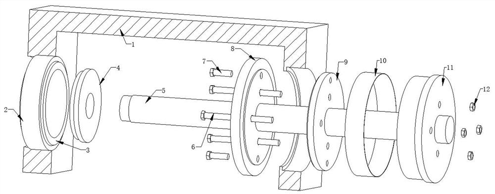
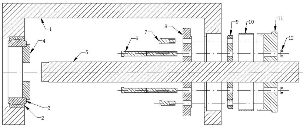
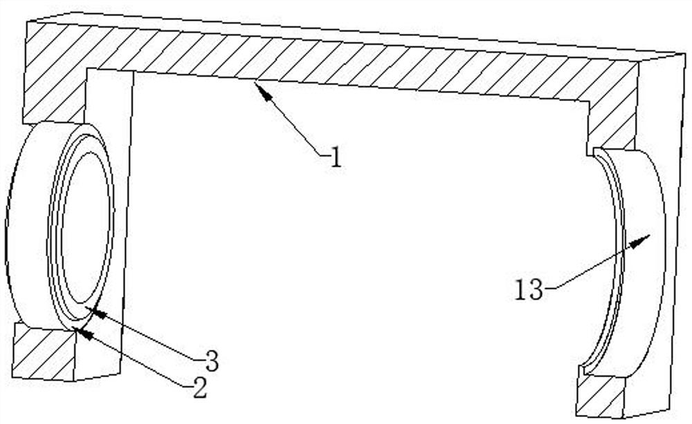
[0038] The main structure of this embodiment, such as figure 1 , figure 2 As shown, it includes a frame beam 1, a centering rod 5 is interspersed in the middle of the frame beam 1, the left end of the centering rod 5 is detachably embedded in the beam column on the left side of the frame beam 1, and the right end of the centering rod 5 penetrates the frame On the beam column on the right side of the beam 1, the centering rod 5 is embedded with a supporting plate 8, a pressing plate 9, and a thrust plate 11 from left to right; the supporting plate 8, the pressing plate 9, and the thrust plate 11 are all provided There are through holes with matching positions, the number of said through holes is at least three, and the centers of any three through holes are not on the same straight line, a long screw 6 is embedded in the through hole, and one end of the long screw 6 is set There is a compression nut 12, through the cooperation of the long screw rod 6 and the compression nut 1...


PUM


Abstract

The invention discloses an installation device for an ultra-thin-walled bush, which comprises a frame beam, a centering rod is interspersed in the middle of the frame beam, the left end of the centering rod can be detachably embedded in the beam column on the left side of the frame beam, and the right end of the centering rod penetrates the frame On the beam column on the right side of the beam, the centering rod is embedded with a supporting plate, a pressing plate, and a thrust plate from left to right; The number of them is at least three, and the centers of any three through holes are not on the same straight line. A long screw is embedded in the through hole, and a compression nut is provided at one end of the long screw. Through the cooperation of the long screw and the compression nut, The supporting plate, the pressing plate and the thrust plate are fixed as a whole, and they are embedded in the inner hole of the beam column on the right side of the frame beam; the left side of the thrust plate is a boss, and a centering bush is nested on the boss. The invention provides an installation device for an ultra-thin-wall bush, which can ensure the rigidity during the installation process of the bush, and can also ensure the fitting degree between the bush and the inner hole after the bush is installed and the dimensional accuracy requirements.

Description

technical field [0001] The invention relates to the technical field of installation of precision parts, in particular to an installation device and an installation method of an ultra-thin-wall bush. Background technique [0002] There are a large number of rotating parts in the aircraft structure, such as canards, vertical tails, etc. These rotating parts are installed in the bearing holes on the aircraft frame beam through the rotating shaft beam. The frame beam on which the rotating shaft is installed is a large structural part with high value. The bearing mounting holes on the frame beam may be oversized during manufacture or the aircraft has been used for a period of time. At this time, it is basically impossible to replace the frame beam as a whole. Therefore, it is necessary to install ultra-thin-wall bushings in the oversized bearing mounting holes to solve the problem. Hole oversized problem. However, because the wall thickness of the bushing is too thin, it is easi...

Claims


Application Information

Patent Timeline
Patent Type & Authority Patents(China)
IPC IPC(8): B23P19/02
CPCB23P19/02
Inventor 刘陨双李成华韦煜萍张林包宗明付杰刘祖智
Owner CHENGDU AIRCRAFT INDUSTRY GROUP
Why Eureka
Try Eureka