
Camera control method and display equipment

A display device and camera technology, applied in image communication, color TV parts, TV system parts, etc., can solve problems such as inability to focus and position, and unable to capture portrait images

Inactive Publication Date: 2020-09-15
HISENSE VISUAL TECH CO LTD
View PDF4 Cites 9 Cited by
  • Summary
  • Abstract
  • Description
  • Claims
  • Application Information

AI Technical Summary

Problems solved by technology

[0005] The present application provides a method for controlling a camera and a display device to solve the problem that the existing display device cannot achieve focus positioning based on a portrait, resulting in the inability to capture an image centered on the portrait.

Method used


Image

  • Camera control method and display equipment
  • Camera control method and display equipment
  • Camera control method and display equipment

Examples


Embodiment Construction

[0110] In order to make the purpose, implementation and advantages of the application clearer, the following will clearly and completely describe the exemplary embodiments of the application in conjunction with the accompanying drawings in the exemplary embodiments of the application. Obviously, the described exemplary embodiments It is only a part of the embodiments of the present application, but not all the embodiments.

[0111] Based on the exemplary embodiments described in this application, all other embodiments obtained by persons of ordinary skill in the art without making creative efforts fall within the protection scope of the appended claims of this application. In addition, although the disclosures in this application are introduced as exemplary one or several examples, it should be understood that each aspect of these disclosures can also independently constitute a complete implementation.

[0112] It should be noted that the brief description of the terms in this a...


PUM


Abstract

The invention discloses a camera control method and display equipment, and the method comprises the steps: enabling a controller to carry out the recognition of a specified image collected by a camera, ing a portrait region position, and calculating the azimuth distance between the region center of the portrait region position and the image center of the specified image; if the azimuth distance exceeds an azimuth set threshold, calculating a target adjustment angle of the camera according to the azimuth distance and shooting parameters of the camera; and adjusting the shooting angle of the camera based on the target adjustment angle of the camera, so as to enable the portrait of the person to be located in the central area of the specified image acquired by the camera. Visibly, according to the method and the display equipment, character position information is accurately recognized through camera image detection, the portrait position is automatically focused and positioned, the shooting angle of the camera is finely adjusted from the horizontal direction and the vertical direction, the portrait of the character is located in the center of the image shot by the camera, and therefore it is guaranteed that the character in the displayer image is centered.

Description

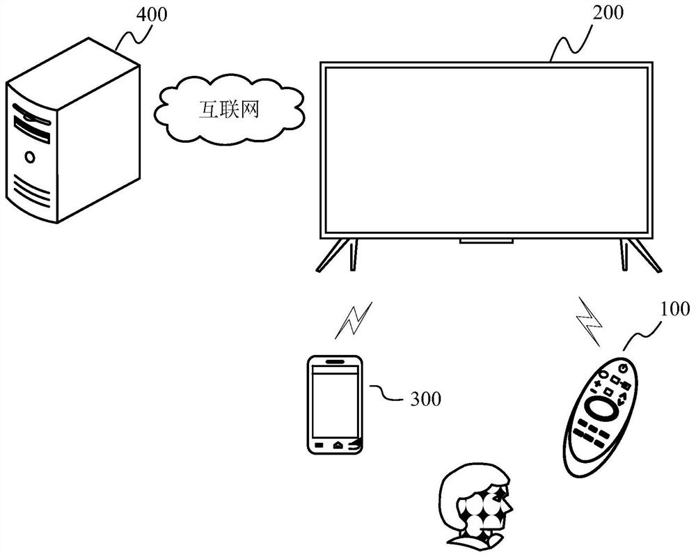
technical field [0001] The present application relates to the technical field of television software, in particular to a method for controlling a camera and a display device. Background technique [0002] With the rapid development of display devices, the functions of display devices will become more and more abundant, and the performance will become more and more powerful. For example, the display device can implement functions such as network search, IP TV, BBTV, video on demand (VOD), digital music, network news, and network video calling. However, when the display device is used to realize the network video call function, a camera needs to be installed on the display device to realize the collection of the user's image. [0003] Currently, the camera installed on the display device can be external or built-in, but no matter which installation method is used, the camera is fixedly installed on the display device. Due to the limited viewing angle of the camera, the previ...

Claims


Application Information

Patent Timeline
Patent Type & Authority Applications(China)
IPC IPC(8): H04N5/232
CPCH04N23/675H04N23/67H04N23/62H04N23/611H04N23/69
Inventor 杨鲁明王依林朱铄孙永江
Owner HISENSE VISUAL TECH CO LTD
Learn More