


Quick Research
Generate reliable direction feasibility study reports for your R&D in just a few steps.

Technical Q&A
Discover and master advanced knowledge NOW. Basics, ideas, possibilities, all at once.

Find Solutions
As an expert in R&D theories, this can generate solutions to your technical problems instantly.

Evaluate Feasibility
Analyze your overall solution with one click, know your potential R&D risks in advance.

Monitor Landscape
Get weekly tech updates, stay abreast of the latest tech innovations and key insights.
Bus capacitor pre-charging circuit and method, frequency converter and air conditioning equipment
A pre-charging circuit and bus capacitor technology, applied in battery circuit devices, current collectors, circuit devices, etc., can solve the problems of circuit impact and large instantaneous current during charging and charging, so as to adjust charging current, improve safety, and flexibly charge current. Effect
- Summary
- Abstract
- Description
- Claims
- Application Information
AI Technical Summary
Problems solved by technology
Method used
Image


Examples
Embodiment 1
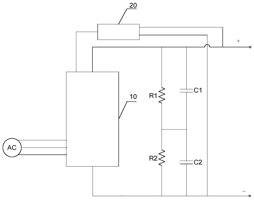
[0054]This embodiment provides a bus capacitor pre-charging circuit. The number of bus capacitors is at least two. In this embodiment, the DC bus includes a first bus capacitor C1 and a second bus capacitor C2, and the first bus capacitor C1 and The second bus capacitor C2 is connected in series between the first line and the second line of the DC bus. The first bus capacitor C1 is connected in parallel to set the first equalizing resistor R1, and the two ends of the second bus capacitor C2 are connected in parallel to set the second equalizing resistor. piezoresistor R2, in order to realize the charging of the above-mentioned first bus capacitor C1 and second bus capacitor C2, figure 1 It is a structural diagram of the bus capacitor pre-charging circuit according to the first embodiment of the present invention, as figure 1 As shown, the circuit includes:
[0055] The charging module 10, the input end of the charging module 10 is connected to the AC power supply, the output ...
Embodiment 2
[0059] This embodiment provides another bus capacitor pre-charging circuit, figure 2 It is a structural diagram of the bus capacitor pre-charging circuit according to the second embodiment of the present invention. In order to realize the charging of the DC bus capacitor while realizing the rectification of the three-phase AC, as figure 2 As shown, the charging module includes three charging units arranged in parallel: the first charging unit 101, the second charging unit 102 and the third charging unit 103, the above-mentioned first charging unit 101, the second charging unit 102 and the third charging unit The unit 103 is sequentially connected to the first phase line, the second phase line and the third phase line of the AC power supply, and the three-phase AC rectification is realized through the first charging unit 101, the second charging unit 102 and the third charging unit 103. Rectify, output a variable current, and charge the bus capacitor through the variable curr...
Embodiment 3
[0061] This embodiment provides another bus capacitor pre-charging circuit, image 3 It is a structural diagram of a bus capacitor pre-charging circuit according to the third embodiment of the present invention, as image 3 As shown, in the first charging unit 101, the second charging unit 102 and the third charging unit 103, each charging unit includes thyristors and diodes connected in series in the same direction, and the first phase line of the AC power supply AC is connected to the first charging unit 101 between the thyristor T1 and the diode D1; the second phase line of the AC power supply AC is connected between the thyristor T2 and the diode D2 in the second charging unit 102; the third phase line of the AC power supply AC is connected to the third charging unit 103 between thyristor T3 and diode D3. The output terminal of the controller 20 is respectively connected to the control terminal of the thyristor T1, the control terminal of the thyristor T2 and the control ...
PUM
 Abstract
Description
Claims
Application Information
 - R&D Engineer
- R&D Manager
- IP Professional
- Industry Leading Data Capabilities
- Powerful AI technology
- Patent DNA Extraction
Browse by: Latest US Patents, China's latest patents, Technical Efficacy Thesaurus, Application Domain, Technology Topic, Popular Technical Reports.
© 2024 PatSnap. All rights reserved.Legal|Privacy policy|Modern Slavery Act Transparency Statement|Sitemap|About US| Contact US: help@patsnap.com