Pantograph application maintenance contact force measurement system and method

A measuring system and pantograph technology, applied in force/torque/work measuring instruments, measuring devices, instruments, etc., can solve the problem that it is difficult to ensure vertical downward and uniform motion, and the power acquisition equipment is inconvenient to move up and down the roof. , It is difficult to realize the problems such as the convenient generation of records and subsequent data, automatic aggregation, mining and analysis, etc., to achieve the effects of automatic processing of measurement results, high degree of controllability of job management, and small human interference factors.

Pending Publication Date: 2020-09-15
陈振虹
View PDF0 Cites 1 Cited by
  • Summary
  • Abstract
  • Description
  • Claims
  • Application Information

AI Technical Summary

Problems solved by technology

Take three points in the process of rising and falling, and measure the average value of these two forces at the end of six sets of data, which is the approximate value of the contact force. This method has the following problems: (1) Manual measurement, with certain human factors , the degree of standardization is not high, and it is not easy to manage
(2) It is difficult to ensure vertical downward and uniform movement by using the hand-pulled spring scale. Because the hand-pulled scale is unstable, the readings will also change
Job results are manually recorded step by step, which is too cumbersome to realize the convenient generation of record sheets and the automatic summary, mining and analysis of subsequent data
(3) The pantograph contact force automatic measurement equipment used in the field generally adopts the motor drive scheme, the reliability is not high, the quality of the equipment is relatively high, and it is inconvenient to obtain power supply, transport the equipment on and off the roof, and move in the various lanes of the maintenance depot

Method used


Image

  • Pantograph application maintenance contact force measurement system and method
  • Pantograph application maintenance contact force measurement system and method
  • Pantograph application maintenance contact force measurement system and method

Examples


Embodiment Construction

[0041] In order to make the object, technical solution and advantages of the present invention clearer, the present invention will be further described in detail below in conjunction with the accompanying drawings and embodiments. It should be understood that the specific embodiments described here are only used to explain the present invention, not to limit the present invention. In addition, the technical features involved in the various embodiments of the present invention described below can be combined with each other as long as they do not constitute a conflict with each other.

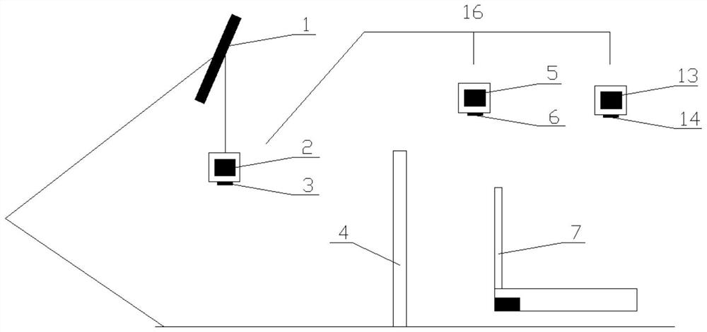
[0042] Such as figure 1 As shown, the embodiment of the present invention provides a pantograph operation and maintenance contact force measurement system, including a lifting mass unit 16 and a data processing device 7 . Wherein, the lifting mass unit 16 is suspended on the pantograph head, and the data processing device 7 is set within the field of view of the lifting mass unit 16, so as to m...


PUM


Abstract

The invention discloses a pantograph application maintenance contact force measurement system. The system comprises a lifting mass unit (16), and a data processing device (7) arranged in the vision field range of the lifting mass unit (16). The data processing device (7) comprises a positioning module, the positioning module comprises a coordinate measuring unit (8) and a timing unit (9), and thecoordinate measuring unit (8) comprises a magnetostriction displacement sensor (4); the data processing device (7) comprises a control module in communication connection with the positioning module; and the control module comprises a communication unit (10), a comprehensive calculation processing unit (11) and a display and output interface unit (12). Non-contact measurement is achieved, measurement precision is high, operation is easy, equipment is reliable and portable, compatibility with various vehicle types can be achieved at the same time, field operation management controllability is high, and a work order record is automatically generated; and a basic platform is further provided for expanding comprehensive data mining and analysis, realizing health management and the like.

Description

technical field [0001] The invention belongs to the field of operation and maintenance of EMUs, and more specifically relates to a contact force measurement system and method for operation and maintenance of pantographs. Background technique [0002] High-speed railways receive power by contacting the catenary with pantographs installed on the roof of high-speed trains as power collectors. The pantograph is the core component of the high-speed EMU to receive catenary power. Especially in the high-speed electrified railway system, it must maintain a stable current receiving state, that is, a certain contact pressure between the pantograph and the contact wire is required. When the contact pressure is too high, the lifting amount of the contact wire is too large, causing the contact wire to be partially bent, causing fatigue damage to the contact wire, and at the same time increasing the wear of the contact wire, causing pantograph-catenary accidents in serious cases; When it...

Claims


Application Information

Patent Timeline
IPC IPC(8): G01L5/00
CPCG01L5/0028
Inventor 陈振虹罗果雷羽李文峰
Owner 陈振虹
Why Eureka
Try Eureka