Method for calibrating and compensating installation errors of single-axis gyroscope
A technology of installation error and gyroscope, which is applied in the field of installation error of fiber optic gyroscope and its inertial measurement device, can solve problems such as calibration and compensation, failure to establish installation error equation, and inability to improve compensation accuracy, improve test efficiency, and reduce processing difficulty Effect
- Summary
- Abstract
- Description
- Claims
- Application Information
AI Technical Summary
Problems solved by technology
Method used
Image
Examples
Embodiment 1
[0064] A method for calibrating and compensating an installation error of a single-axis gyroscope, comprising the following steps:
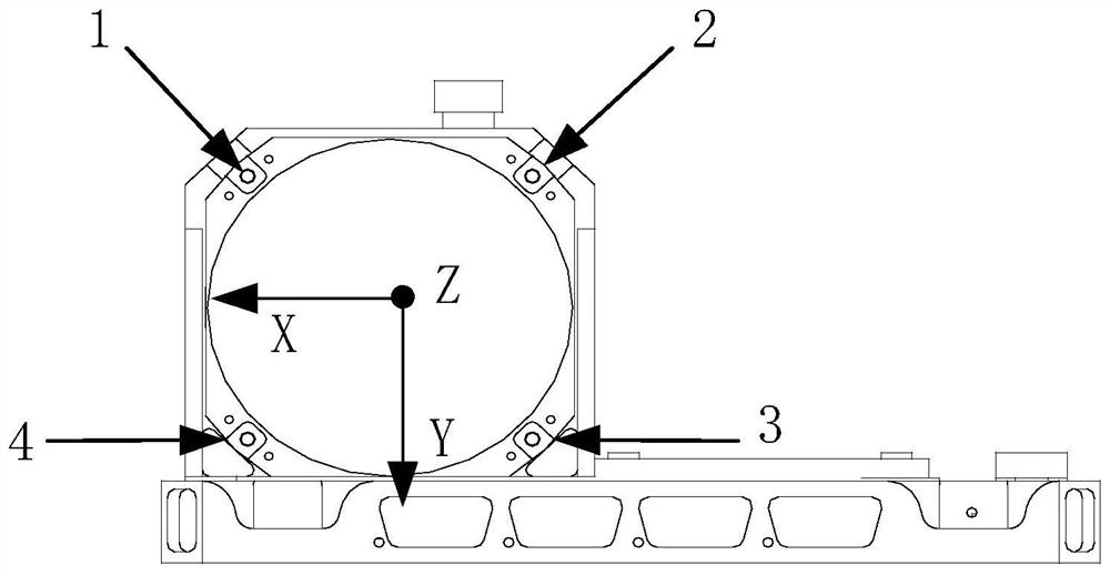
[0065] (1) Place the X-axis of the gyro-inertial measurement device facing the sky and the sensitive axis (Z-axis) of the gyroscope facing south, and place it on the rate turntable;
[0066] (2) Rotate the turntable in positive and negative directions respectively, and the input angular rate of the turntable is ω x and -ω x , the running time is t;
[0067] (3) Obtain the installation error of the gyro sensitive axis relative to the X axis through calculation;
[0068] (4) Place the Y-axis of the gyro inertial measurement device facing the sky and the sensitive axis of the gyro facing south, and place it on the rate turntable;
[0069] (5) Repeat step (2);
[0070] (6) Obtain the installation error of the gyro sensitive axis relative to the Y axis through calculation;
[0071] (7) Through calculation, the thickness of the gasket that needs t...
Embodiment 2
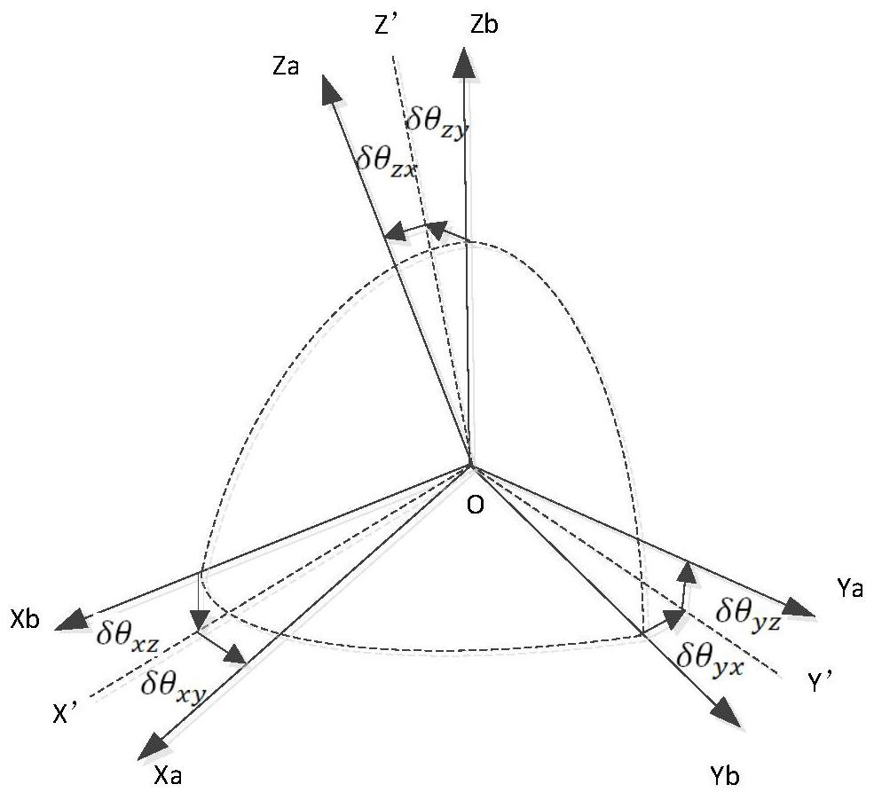
[0084] The installation error is an important factor affecting the measurement accuracy of the fiber optic gyroscope inertial measurement device. Therefore, in order to improve the measurement accuracy of the inertial measurement device, it is necessary to compensate the installation error. The present invention proposes an installation error calibration and compensation method for the single-axis gyro assembly. The method relies on the projection of the angular velocity caused by the installation error on the sensitive axis to measure the installation error angle relative to each axial direction, and then calculates the For the height that needs to be compensated, the feeler gauge is used to process the gasket that meets the compensation requirements, so as to reduce the installation error and improve the measurement accuracy of the gyro.
[0085] The installation error calibration and compensation method of the present invention comprises the following steps:
[0086] (1) Us...
Embodiment 3
[0097] Applying the method of embodiment 1 or 2, a method for calibration and compensation of single-axis gyroscope installation errors, the steps of the method include:
[0098] (1) Using tooling, place the X-axis of the gyro inertial measurement device facing the sky and the sensitive axis of the gyro facing south, and place it on the rate turntable;
[0099] (2) Rotate the turntable in positive and negative directions respectively, the input angular rate of the turntable is 30° / s and -30° / s, and the running time is 48s;
[0100] (3) Through calculation, the installation error of the gyro sensitive axis relative to the X axis is -2.4000′;
[0101] (4) Place the Y-axis of the gyro inertial measurement device facing the sky and the sensitive axis of the gyro facing south, and place it on the rate turntable;
[0102] (5) Repeat step (2);
[0103] (6) Through calculation, the installation error of the gyro sensitive axis relative to the Y axis is -3.0014';
[0104] (7) Throug...
PUM
 Abstract
Description
Claims
Application Information
 - Generate Ideas
- Intellectual Property
- Life Sciences
- Materials
- Tech Scout
- Unparalleled Data Quality
- Higher Quality Content
- 60% Fewer Hallucinations
Browse by: Latest US Patents, China's latest patents, Technical Efficacy Thesaurus, Application Domain, Technology Topic, Popular Technical Reports.
© 2025 PatSnap. All rights reserved.Legal|Privacy policy|Modern Slavery Act Transparency Statement|Sitemap|About US| Contact US: help@patsnap.com


