Monitoring device for timely removing shelter

A technology for monitoring equipment and blocking objects, which is applied in the field of monitoring equipment that removes blocking objects in a timely manner, can solve the problems of monitoring work difficulties, fixed camera shooting areas, and many monitoring dead angles, so as to reduce monitoring dead angles and ensure monitoring image quality. The effect of improving the quality of monitoring

Inactive Publication Date: 2020-09-15
福清市冠恒电子科技有限公司
View PDF0 Cites 3 Cited by
  • Summary
  • Abstract
  • Description
  • Claims
  • Application Information

AI Technical Summary

Problems solved by technology

[0003] Surveillance cameras at this stage are usually exposed to the external environment, and there will be occluders in front of the lens to block the surveillance images, causing troubles to the surveillance work, and the shooting area of ​​the camera is fixed, and there are many dead spots in the surveillance

Method used


Image

  • Monitoring device for timely removing shelter
  • Monitoring device for timely removing shelter
  • Monitoring device for timely removing shelter

Examples


Embodiment Construction

[0018] All features disclosed in this specification, or steps in all methods or processes disclosed, can be combined in any way, except for mutually exclusive features and or steps.

[0019] Combine below Figure 1-5 The present invention is described in detail, and for convenience of description, the orientations mentioned below are now stipulated as follows: figure 1 The up, down, left, right, front and back directions of the projection relationship itself are consistent.

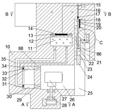
[0020] A monitoring device for removing obstructions in time according to the device of the present invention includes a box body 10, the bottom surface of the box body 10 is provided with a transparent slider groove 25 with an opening downward, and a transparent slider groove 25 is slidably connected to the inside of the transparent slider groove 25. Block 86, the top of the transparent slider 86 is symmetrically fixedly connected with the right pull cord 19, the top surface of the transparent slider 86...


PUM


Abstract

The invention discloses a monitoring device for timely removing a shelter. The device comprises a box body, wherein the bottom surface of the box body is provided with a transparent sliding block groove, a transparent sliding block is connected in the transparent sliding block groove, right pull ropes are connected to the top surface of the transparent sliding block groove in a front-back symmetric mode, the top surface of the transparent sliding block is connected to the transparent sliding block groove through a first spring, the top wall of the transparent sliding block groove is provided with a first sliding groove, the first sliding groove is internally connected with a sliding rod, the top end of the slide rod is connected to a metal block, the top surface of the sliding rod is connected with the first sliding groove through a second spring, the second spring is connected with the transparent sliding block, eight second sliding grooves are uniformly arranged at the bottom surfaceof the transparent sliding block in a front-back mode, the bottom end of the sliding rod is located in the second sliding groove, transparent clamping blocks are connected in the second sliding grooves, clamping grooves are formed in the right end faces of the transparent clamping blocks, and the top surfaces of the transparent clamping blocks are connected with the second sliding grooves throughthird springs. A shelter in front of a lens can be processed in time to prevent a monitoring image from being blocked, and a camera slowly rotates to expand a monitoring range.

Description

technical field [0001] The invention relates to the related technical field of monitoring equipment, in particular to a monitoring equipment for removing obstructions in time. Background technique [0002] A typical TV monitoring system is mainly composed of front-end equipment and back-end equipment. Cameras and lenses are essential to realize monitoring site image acquisition. Back-end equipment can be further divided into central control equipment and sub-control equipment. [0003] Surveillance cameras at this stage are usually exposed to the external environment, and there will be occluders in front of the lens to block the surveillance images, which will cause troubles to the surveillance work. Moreover, the shooting area of ​​the camera is fixed, and there are many dead spots in the surveillance. Contents of the invention [0004] In view of the deficiencies of the above-mentioned technologies, the present invention proposes a monitoring device for removing obstruc...

Claims


Application Information

Patent Timeline
IPC IPC(8): F16M11/04F16M11/08F16M11/18H04N5/225
CPCF16M11/04F16M11/08F16M11/18H04N23/50
Inventor 高伦
Owner 福清市冠恒电子科技有限公司
Why Eureka
Try Eureka