Anti-sputtering grinding device for door and window hardware machining

An anti-sputtering and hardware technology, applied in the field of hardware processing, can solve the problems of users' facial injuries and limited protection range, and achieve the effects of stable operation, simple structure and guaranteed locking effect.

Inactive Publication Date: 2020-09-15
筑岚门窗设计(杭州)有限公司
View PDF6 Cites 0 Cited by
  • Summary
  • Abstract
  • Description
  • Claims
  • Application Information

AI Technical Summary

Problems solved by technology

[0003] In the prior art, when processing hardware, it is often necessary to use a grinding device to polish some hardware, and most of the users do not have corresponding protection when grinding, so the debris generated during grinding may cause the user In case of facial injuries, some users will use protective glasses for protection. The protection range is limited, and debris and residue will adhere to the glasses after long-term use. Aiming at the deficiencies of the prior art, the present invention discloses an anti-sputtering Grinding device for building door and window hardware processing to solve the above problems

Method used


Image

  • Anti-sputtering grinding device for door and window hardware machining
  • Anti-sputtering grinding device for door and window hardware machining
  • Anti-sputtering grinding device for door and window hardware machining

Examples


Embodiment 1

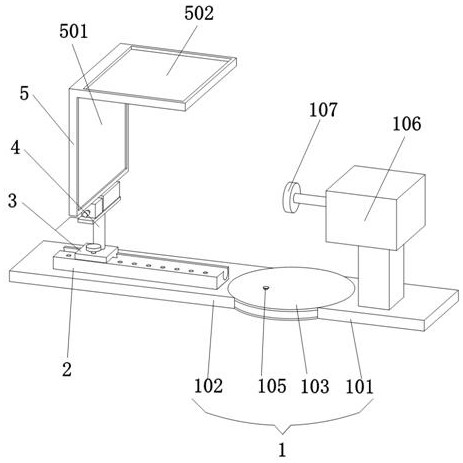
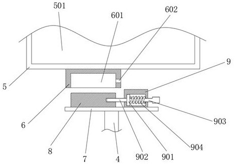
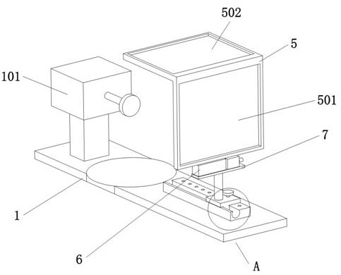
[0026] An embodiment of the present invention provides a sputter-proof grinding device for processing architectural door and window hardware, such as Figure 1-6 As shown, the base plate 1 and the protective frame 5 are included, the top of the base plate 1 is provided with a grinder main body 106, the top of the base plate 1 is fixedly connected with a guide rail 2, the upper surface of the guide rail 2 is slidably connected with a sliding plate 3, and the upper surface of the sliding plate 3 The support column 4 is fixedly connected, the top of the support column 4 is fixedly connected with the support plate 7, the top of the support plate 7 is fixedly connected with the cover block 8, and the bottom of the protective frame 5 is fixedly connected with the block 6 corresponding to the cover block 8, The bottom of the clamping block 6 is provided with a clamping slot 601, and the clamping block 6 is sleeved on the sleeve block 8 through the clamping slot 601. The top of the sup...

Embodiment 2

[0034]The applicant found in practice that the above solution also has the following problems: when the workpieces to be polished have different shapes, when placing the workpieces for grinding, the placement of the workpieces will be limited between the main body of the grinder and the protective frame 5, and it is even difficult to grind Therefore, the applicant divides the bottom plate 1 into a fixed plate 101 and a rotating plate 102 that is rotatably connected with the fixed plate 101. The fixed plate 101 is provided with a hollow circular turntable 103 at the joint with the rotating plate 102, and the rotating plate 102 extends into the The part in the circular turntable 103 is provided with several locking holes 104 a week, and the circular turntable 103 is provided with a pin hole, and the circular turntable 103 is provided with a pin 105 matched with the pin hole, and the pin 105 passes through the pin hole and the locking hole The position of 104 is corresponding, the...

Embodiment 3

[0036] The applicant also found that when grinding some hardware, it is possible to polish multiple positions of the hardware. At this time, it is necessary to repeatedly adjust the side glass 501 and the top glass 502, which is cumbersome. A strap is set on the protective frame 5 and tied together with the human body. At this time, when grinding, the rotating plate will follow the rotation of the person, so as to adapt to the situation that the hardware needs to be polished in multiple positions, so that the whole grinding protection is more flexible. Stronger.

[0037] Concrete work process of the present invention is as follows:

[0038] When the user uses the grinder main body 106 on the bottom plate 1 to grind the hardware, the pin 105 is first taken out, and the rotating plate 102 rotates around the circular turntable 103 through the rotating shaft 108, so that the side glass 501 and the top glass 502 are polished around The main body 106 of the machine rotates, and aft...


PUM


Abstract

The invention discloses an anti-sputtering grinding device for door and window hardware machining, and relates to the field of hardware machining. The anti-sputtering grinding device for door and window hardware machining comprises a bottom plate and a protective frame, the top of the bottom plate is fixedly connected with a guide rail, the upper surface of the guide rail is slidably connected with a sliding plate, the upper surface of the sliding plate is fixedly connected with a supporting column, the top of the supporting column is fixedly connected with a supporting plate, the top of the supporting plate is fixedly connected with a sleeve block, the bottom of the protecting frame is fixedly connected with a clamping block, the clamping block sleeves the sleeve block, and the top of thesupporting plate is provided with a locking mechanism. According to the anti-sputtering grinding device for door and window hardware machining, the position of the protective frame can be conveniently adjusted by a user, then the face of the user can be protected, injury of the user due to debris splashing during grinding of hardware is prevented, the protective frame is convenient to disassemble, install and wash, and debris and residues attached to the outer surface of the protective frame are convenient to remove.

Description

technical field [0001] The invention relates to the technical field of hardware processing, in particular to a sputter-proof polishing device for processing architectural door and window hardware. Background technique [0002] Hardware accessories refer to machine parts or components made of hardware, as well as some small hardware products, which can be used alone or as auxiliary tools. [0003] In the prior art, when processing hardware, it is often necessary to use a grinding device to polish some hardware, and most of the users do not have corresponding protection when grinding, so the debris generated during grinding may cause the user In case of facial injuries, some users will use protective glasses for protection. The protection range is limited, and debris and residue will adhere to the glasses after long-term use. Aiming at the deficiencies of the prior art, the present invention discloses an anti-sputtering A grinding device for processing building door and windo...

Claims


Application Information

Patent Timeline
Patent Type & Authority Applications(China)
IPC IPC(8): B24B19/00B24B41/02B24B55/00
CPCB24B19/00B24B41/02B24B55/00
Inventor 沈阳
Owner 筑岚门窗设计(杭州)有限公司
Why Eureka
Try Eureka