
Touch display device

A technology of a touch display device and a touch layer, which is applied in the fields of instruments, electrical digital data processing, electrical components, etc., can solve the problems of affecting touch sensitivity and other performance, large parasitic capacitance, etc., so as to improve the touch point reporting rate, The effect of reducing parasitic capacitance

Pending Publication Date: 2020-09-11
WUHAN CHINA STAR OPTOELECTRONICS SEMICON DISPLAY TECH CO LTD
View PDF0 Cites 4 Cited by
  • Summary
  • Abstract
  • Description
  • Claims
  • Application Information

AI Technical Summary

Problems solved by technology

[0005] The purpose of the present application is to provide a touch display device to solve the problem that the small distance between the cathode on the support column and the touch electrode leads to a large parasitic capacitance and affects touch sensitivity and other performance problems

Method used


Image

  • Touch display device
  • Touch display device
  • Touch display device

Examples


Embodiment Construction

[0027] The technical solutions in the embodiments of the present application will be clearly and completely described below in conjunction with the drawings in the embodiments of the present application. Apparently, the described embodiments are only some of the embodiments of this application, not all of them. Based on the embodiments in this application, all other embodiments obtained by those skilled in the art without making creative efforts belong to the scope of protection of this application.

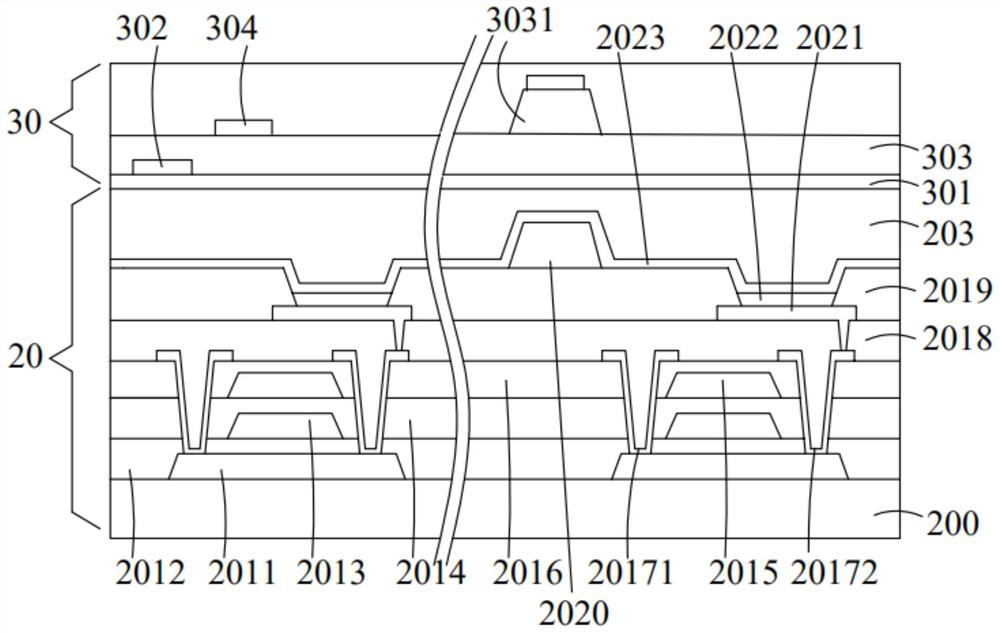
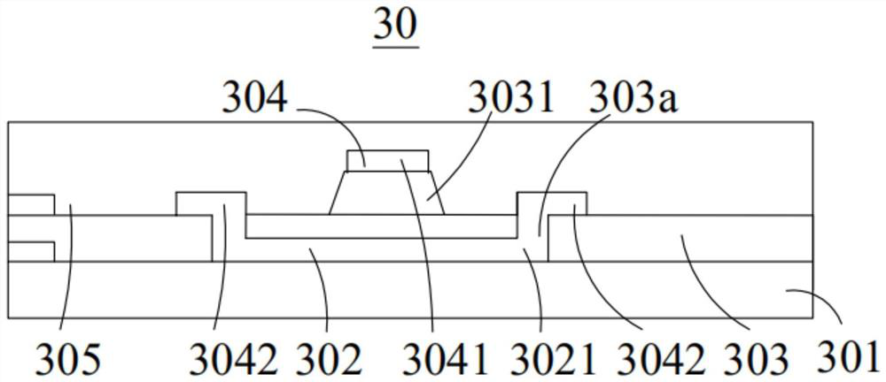
[0028] see figure 2 , which is a schematic cross-sectional view of the touch display device of the present application. The touch display device includes an OLED display panel 20 and a touch layer 30 . The OLED display panel 20 may be a flexible OLED display panel, or a rigid OLED display panel. The touch layer 30 is located on one side of the OLED display panel 20 . Specifically, the touch layer 30 is located on the light emitting side of the OLED display panel 20 .

[002...


PUM


Abstract

The present invention provides a touch display device, which comprises: an organic light emitting diode display panel including a support pillar and a cathode, wherein a part of the cathode is formedon the support pillar; and a touch layer positioned on one side of the organic light emitting diode display panel, wherein the touch layer comprises an insulating layer and a first conducting layer, aprotrusion is arranged on the insulating layer, part of the first conducting layer is located on the side, away from the cathode, of the protrusion, and the orthographic projection of the protrusionon the touch display device at least partially coincides with the orthographic projection of the support pillar on the touch display device. According to the touch display device, the protrusion is arranged on the insulating layer of the touch layer, so that the distance between the cathode on the support pillar and the first conducting layer on one side of the protrusion on the insulating layer is increased, so that the parasitic capacitance between the first conducting layer arranged corresponding to the support pillar and the cathode on the support pillar is reduced, and the touch reportingrate of the touch display device is increased.

Description

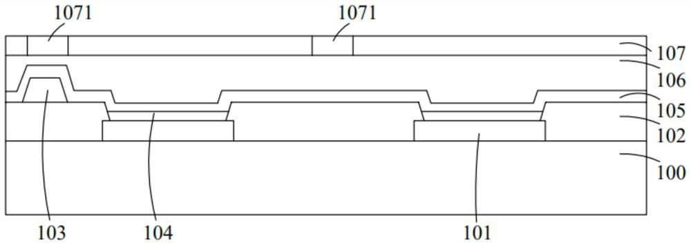
technical field [0001] The present application relates to the technical field of touch display, in particular to a touch display device. Background technique [0002] Flexible organic light-emitting diode (Organic Light-Emitting Diode, OLED) display has the advantages of active light emission, large viewing angle, wide color gamut, high brightness, fast response, low power consumption, and structural bendability. Flexible organic light-emitting diode display It is becoming more and more popular in the market, gradually replacing liquid crystal displays and becoming the mainstream of display technology. [0003] Flexible organic light-emitting diode displays are divided into top-emitting and bottom-emitting types according to their light-emitting positions. At present, the top-emission organic light emitting diode display is the mainstream of the mass production technology of the organic light emitting diode display. Such as figure 1 , which is a schematic diagram of a con...

Claims


Application Information

Patent Timeline
Patent Type & Authority Applications(China)
IPC IPC(8): H01L27/32H01L51/52
CPCH10K59/40H10K59/805H10K59/87G06F3/0412G06F3/0446G06F3/04164G06F2203/04111H10K59/122H10K50/84H10K2102/311
Inventor 叶剑
Owner WUHAN CHINA STAR OPTOELECTRONICS SEMICON DISPLAY TECH CO LTD
Learn More