Injection molding system and injection molding method
An injection molding system and top-tightening technology, applied in the field of plastic injection molding, can solve problems affecting production efficiency and inconvenient removal
- Summary
- Abstract
- Description
- Claims
- Application Information
AI Technical Summary
Problems solved by technology
Method used
Image
Examples
specific Embodiment approach 1
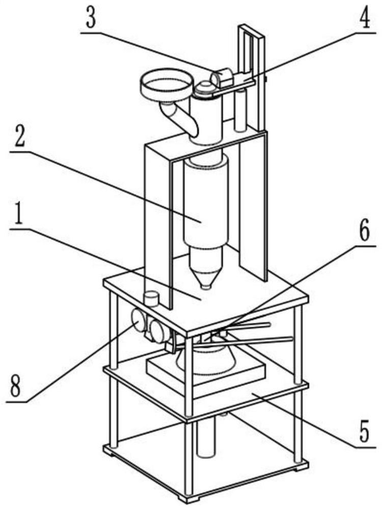
[0037] Such as Figure 1-12 As shown, an injection molding system includes a support frame 1, a melting material mechanism 2, a feeding mechanism 3, an injection mechanism 4, a lower mold frame 5, a top tightening mechanism 6, an adjusting mechanism 7, a slide bar guiding mechanism 8 and an air suction pump 9 , the melting mechanism 2 is fixedly connected to the support frame 1, the injection mechanism 4 is connected to the upper end of the support frame 1, the feeding mechanism 3 is connected to the injection mechanism 4, the feeding mechanism 3 and the melting mechanism 2 sliding connection, the lower mold frame 5 is connected to the lower end of the support frame 1, the clamping mechanism 6 is slidably connected in the lower mold frame 5, the adjustment mechanism 7 is connected to the lower mold frame 5, and the adjustment mechanism 7 It is threadedly connected with the top tightening mechanism 6, the air suction pump 9 is fixedly connected on the lower mold base 5, the air...
specific Embodiment approach 2
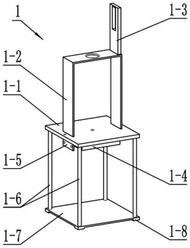
[0040] Such as Figure 1-12 As shown, the support frame 1 includes a main board 1-1, a support plate 1-2, a fixed slide plate 1-3, an upper mold 1-4, a mounting plate 1-5, a support slide bar 1-6, and a bottom plate 1-7 and the base 1-8, the support plate 1-2 is fixedly connected to the upper end surface of the main board 1-1, the fixed slide plate 1-3 is fixedly connected to the upper end of the support plate 1-2, and the upper mold 1-4 and the mounting plate 1-5 are all Fixedly connected to the lower end surface of the mainboard 1-1, four supporting slide bars 1-6 are provided, and the upper ends of the four supporting slide bars 1-6 are fixedly connected to the four corners of the mainboard 1-1 respectively, and the four supporting slide bars 1-6 The lower ends of -6 are respectively fixedly connected to the four corners of the base plate 1-7, and the four corners of the lower end of the base plate 1-7 are provided with a base 1-8;
specific Embodiment approach 3
[0042] Such as Figure 1-12 As shown, the melting mechanism 2 includes a feeding port 2-1, a melting pipe 2-2, a heating pipe 2-3 and an injection cone head 2-4, and the melting pipe 2-2 is fixedly connected to the support plate 1 In the middle of -2, the lower end of the melting material pipe 2-2 is fixedly connected with the injection cone head 2-4, the injection cone head 2-4 is provided with a valve, and the heating pipe 2-3 is fixedly connected with the melting material pipe 2-2 On the outer wall of the pipe, the upper end of the melting material pipe 2-2 is provided with a feeding port 2-1, and the injection cone head 2-4 communicates with the upper mold 1-4;
[0043] The feeding port 2-1 is used to add plastic granules to the device, and the heating pipe 2-3 is used to heat and melt the plastic granules in the melting pipe 2-2.
PUM
 Abstract
Description
Claims
Application Information
 - Generate Ideas
- Intellectual Property
- Life Sciences
- Materials
- Tech Scout
- Unparalleled Data Quality
- Higher Quality Content
- 60% Fewer Hallucinations
Browse by: Latest US Patents, China's latest patents, Technical Efficacy Thesaurus, Application Domain, Technology Topic, Popular Technical Reports.
© 2025 PatSnap. All rights reserved.Legal|Privacy policy|Modern Slavery Act Transparency Statement|Sitemap|About US| Contact US: help@patsnap.com


