Electric stapler

A stapler and electric technology, which is applied in the direction of manufacturing tools, nailing tools, nailing tools, etc., can solve the problems of inconvenient use of manual staplers, non-adjustable distance between paper edges, and insufficient stability of functions, etc., to achieve Low noise, simple mechanism, and stable nailing action

Inactive Publication Date: 2020-09-11
EAGLE SHAOGUAN STATIONERY TECH LTD
View PDF5 Cites 2 Cited by
  • Summary
  • Abstract
  • Description
  • Claims
  • Application Information

AI Technical Summary

Problems solved by technology

[0002] The common office stationery staplers on the market are generally manually typed, which requires manual operation and is inconvenient to use. Therefore, in order to overcome the disadvantages of inconvenient use of manual staplers, electric staplers have appeared on the market. The current electric stapler cannot adjust the paper edge distance during binding. In addition, most of the existing electric staplers use a spur gear structure, which is complex in structure assembly, loud in noise, and not stable enough in function.

Method used


Image

  • Electric stapler
  • Electric stapler
  • Electric stapler

Examples


Embodiment 1

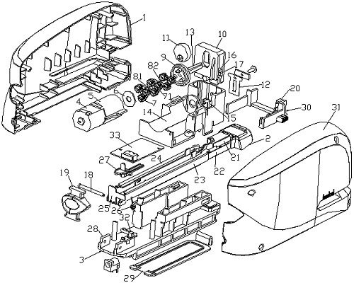
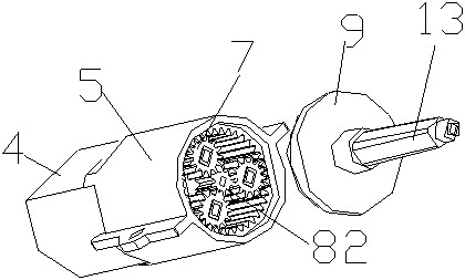
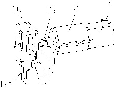
[0035] Such as Figure 1-6 As shown, this embodiment provides an electric stapler, including a left cover 1 and a right cover 31, the left cover 1 and the right cover 31 are fastened together to form an accommodating space, and also includes:

[0036] A stapling mechanism, the stapling mechanism includes a base 3 and a binding frame 2, and the tail end of the base 3 and the binding frame 2 are rotatably connected through a rotating shaft 18;

[0037] A nail pressing mechanism, the said nail pressing mechanism is arranged above the front end of the binding frame 2, and is used to drive the staple mechanism to complete the binding work;

[0038] A driving mechanism, the driving mechanism is arranged above the staple mechanism, the driving mechanism is connected with the nail pressing mechanism through a transmission shaft 13, and the driving mechanism is used to drive the up and down movement of the nail pressing mechanism;

[0039] The distance adjustment block 30, the distanc...


PUM


Abstract

The invention relates to the technical field of office stationery, in particular to an electric stapler. The electric stapler comprises a left cover and a right cover, wherein the left cover and the right cover are buckled to form a containing space, a driving mechanism, a staple pressing mechanism, a control mechanism, a stapling mechanism, a circuit board and a distance adjusting block are arranged in the containing space, the driving mechanism is connected with the staple pressing mechanism through a rotating shaft, the driving mechanism is used for driving the staple pressing mechanism tomove up and down, the stapling mechanism is arranged below the driving mechanism and the staple pressing mechanism, the distance adjusting block is arranged at the position, in front of a staple outlet, of the stapling mechanism, and a paper inlet switch in the control mechanism is arranged on the distance adjusting block. According to the electric stapler, the distance between the staple outlet and the paper inlet switch can be changed by adopting the distance adjusting block, so that the binding paper edge distance is changed, and different binding edge distance requirements can be met.

Description

technical field [0001] The invention relates to the technical field of office stationery, in particular to an electric stapler. Background technique [0002] The common office stationery staplers on the market are generally manually typed, which requires manual operation and is inconvenient to use. Therefore, in order to overcome the disadvantages of inconvenient use of manual staplers, electric staplers have appeared on the market. The current electric stapler cannot adjust the paper edge distance during binding. In addition, the existing electric stapler mostly adopts a spur gear structure, which is complex in structure assembly, noisy, and not stable enough in function. Contents of the invention [0003] The present invention provides an electric stapler aiming at the deficiencies in the prior art, adopting a distance adjusting block to adjust the distance between binding paper edges, adopting a planetary gear structure and a sliding nailing structure, so that the elect...

Claims


Application Information

Patent Timeline
Patent Type & Authority Applications(China)
IPC IPC(8): B25C5/15B25C7/00
CPCB25C5/15B25C7/00
Inventor 陈绍良熊辉雄陈官泰
Owner EAGLE SHAOGUAN STATIONERY TECH LTD
Why Eureka
Try Eureka