Heating and cleaning device for laparoscope
A cleaning device and laparoscope technology, applied in laparoscope, electromechanical device, application, etc., can solve the problems affecting the operation process of patients, poor laparoscope view, lens fogging, etc., to improve safety and practicability, improve Safety, Guarantee the effect of observing the effect
- Summary
- Abstract
- Description
- Claims
- Application Information
AI Technical Summary
Problems solved by technology
Method used
Image
Examples
Embodiment 1
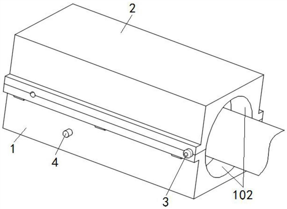
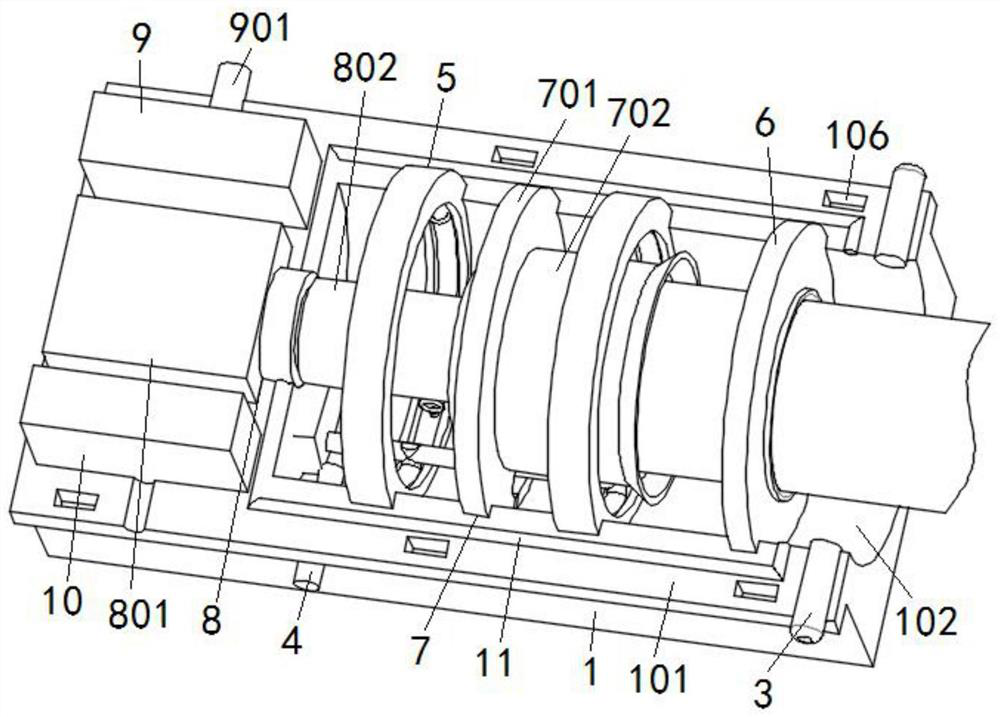
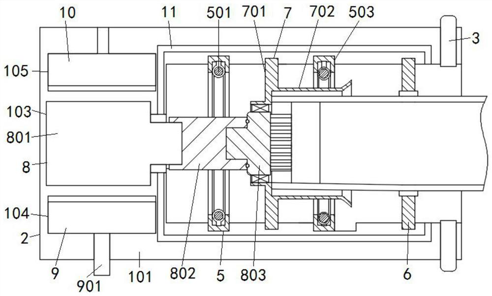
[0035] Such as Figure 1-4 with Figure 8 As shown, the present invention is a heating and cleaning device for laparoscopy, including a base 1 and an upper base 2 engaged with the base 1; flange connecting plates 101 are respectively fixed on the opposite sides of the base 1 and the upper base 2; the base 1 It can be fixed at a place convenient for doctors to defog and clean the laparoscope by screws or cable ties;
[0036] The flange connection plate 101 of the base 1 is uniformly provided with several bayonet sockets 106; the flange connection plate 101 of the upper base 2 is evenly distributed with claws 201 snap-fitted with the bayonet sockets 106; when the upper base 2 is mounted on the base 1, the jaws 201 penetrate the bayonet 106 and engage with the lower surface of the bayonet 106; when people push the jaws 201 on both sides of the upper seat 2, the jaws 201 on both sides of the upper seat 2 approach each other, and the jaws 201 The clamping cooperation with the low...
Embodiment 2
[0058] Such as Figure 9 As shown, the heating assembly 5 includes a circuit board 504 and a U-shaped heating tube 505; the circuit board 504 and the U-shaped heating tube 505 belong to the prior art; and a through hole is opened in the middle of the circuit board 504 for the output shaft of the motor 801 to pass through; The circuit board 504 is fixed on the side inner wall of the semi-blind hole 102 by screws; and the U-shaped heating tube 505 is electrically connected with two U-shaped heating tubes 505; the two U-shaped heating tubes 505 are located between the annular plate 701 and the semi-blind hole. 102, and the two U-shaped heating tubes 505 are located on both sides of the output shaft of the motor 801, which will not affect the installation of the motor 801 in the motor slot 103, nor will it affect the cylindrical cleaning head 803 and the retaining ring assembly. The disassembly of 7 is affected.
PUM
 Abstract
Description
Claims
Application Information
 - R&D
- Intellectual Property
- Life Sciences
- Materials
- Tech Scout
- Unparalleled Data Quality
- Higher Quality Content
- 60% Fewer Hallucinations
Browse by: Latest US Patents, China's latest patents, Technical Efficacy Thesaurus, Application Domain, Technology Topic, Popular Technical Reports.
© 2025 PatSnap. All rights reserved.Legal|Privacy policy|Modern Slavery Act Transparency Statement|Sitemap|About US| Contact US: help@patsnap.com


