A luggage electric brake device

A brake device and technology for luggage, which is applied in the direction of luggage, wheels, travel goods, etc., can solve the problems that the trolley case is easy to slide and touch other passengers, laborious to operate, and inconvenient for users, so as to achieve convenient and labor-saving braking or release of the brake Effect

Active Publication Date: 2022-04-26
DONGGUAN JIANG SHUN SUITCASES & HANDBAGS SPARE PARTS
View PDF0 Cites 0 Cited by
  • Summary
  • Abstract
  • Description
  • Claims
  • Application Information

AI Technical Summary

Problems solved by technology

However, when people take a bus or a train with a trolley case, if the trolley case is placed on the floor in the car, due to the effect of inertia, the trolley case is easy to slide and touch other passengers during the acceleration or deceleration of the vehicle. Inconveniencing the user and, more seriously, potentially injuring other passengers
[0003] Therefore, in order to realize the braking of the suitcase, a manual braking device is designed in the prior art. The device needs to manually pull the brake lever to realize the braking of the wheel group by pulling the transmission line; the previous braking methods exist: relatively laborious and Disadvantages of cumbersome operation

Method used


Image

  • A luggage electric brake device
  • A luggage electric brake device
  • A luggage electric brake device

Examples


Embodiment Construction

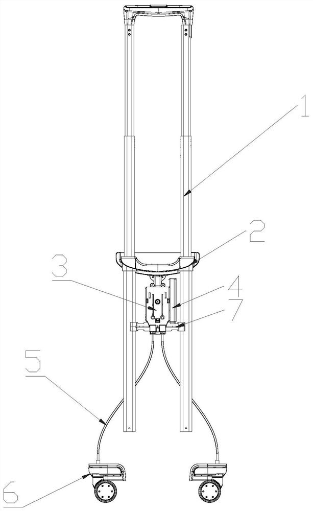
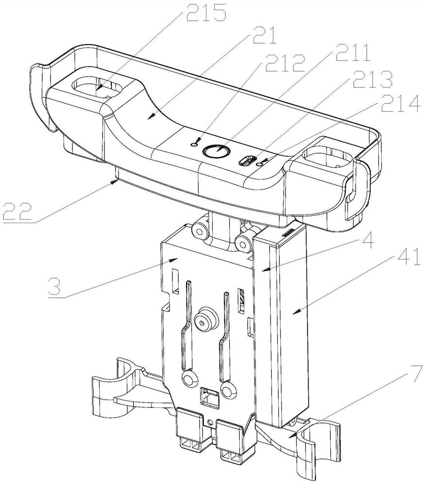
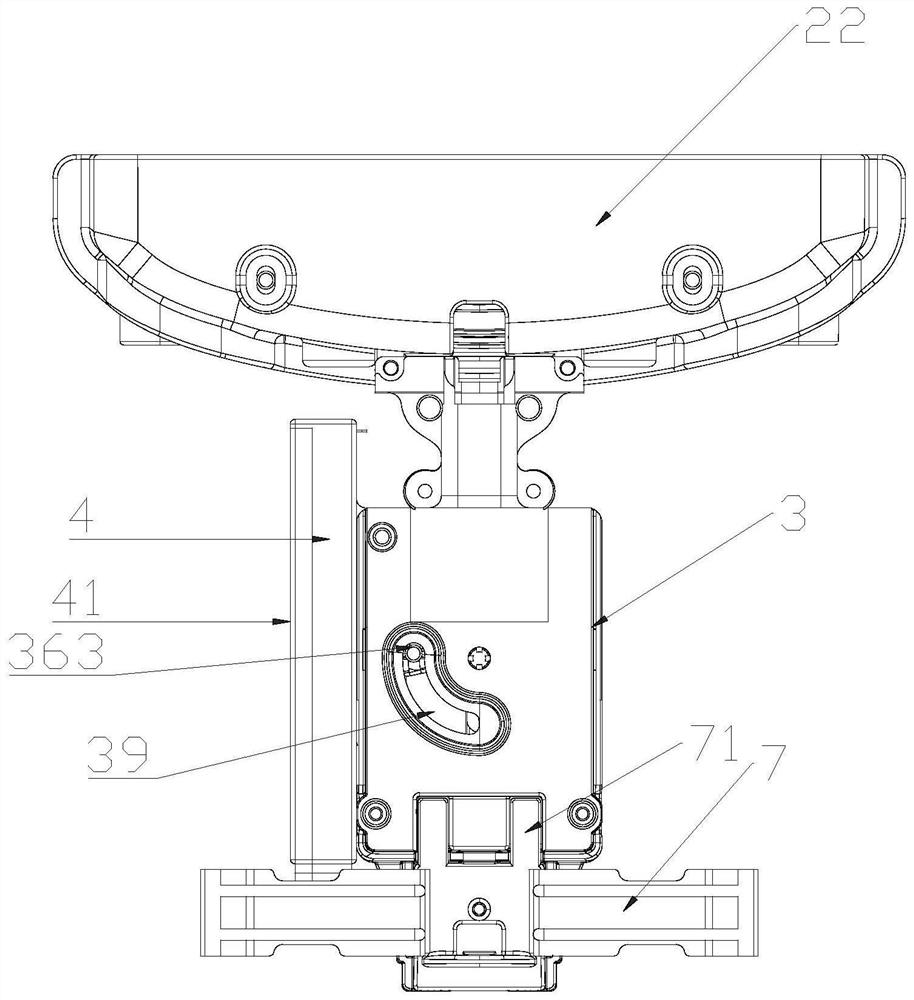
[0022] see Figure 1-7 As shown, an electric brake device for luggage includes a pull rod assembly 1, a brake power device fitted on the pull rod assembly 1, several brake wheel sets 6, and several transmission lines 5; wherein the brake power device includes a power supply device 4, Brake control device 2, electric brake device 3, wherein said brake control device 2 includes a control circuit board electrically connected to the power supply device 4, and a control button 211 electrically connected to the control circuit board; said electric brake device 3 includes a box Seat, the drive motor 31 that is arranged in the box seat and is electrically connected with the control circuit board, the bevel gear 35 that is arranged in the box seat and placed along the horizontal plane, the fan-shaped swing gear that is arranged in the box seat and placed along the vertical plane 36. The lifting slider 37 that is arranged in the box seat and slides freely along the vertical direction; w...


PUM


Abstract

The present application provides an electric brake device for luggage. In the past, wheel group brakes were all manually operated by pushing buttons to brake, which was laborious. The battery is now used as the energy supply, and the output shaft of the drive motor can be driven to drive the bevel gear to rotate only by lightly pressing the control button. The bevel gear meshes with the sector swing gear and drives the lifting cylinder of the sector swing gear to swing along the sector The circumferential movement of the gear will make the lifting slider move up and drive the transmission line to move up and realize the braking of the brake wheel group; when the brake needs to be released, just press the control button again to drive the output shaft of the drive motor to drive the bevel gear Rotating in the opposite direction, the bevel gear meshes with the sector swing gear and drives the lifting cylinder of the sector swing gear to move along the circumference of the sector swing gear, so that the lift slider moves down to drive the transmission line down and releases the brake wheel Set of brakes. Even the process of braking or releasing the brake is very convenient and labor-saving.

Description

technical field [0001] The invention relates to the field of trolley luggage, in particular to an electric brake device for luggage. Background technique [0002] The trolley case is a kind of daily necessities commonly used, and the bottom of it is provided with rollers, which makes pulling convenient and labor-saving, and is very popular among people. However, when people take a bus or a train with a trolley case, if the trolley case is placed on the floor in the car, due to the effect of inertia, the trolley case is easy to slide and touch other passengers during the acceleration or deceleration of the vehicle. Bring inconvenience to the user, what is more serious, also may bump other passengers. [0003] Therefore, in order to realize the braking of the suitcase, a manual braking device is designed in the prior art. The device needs to manually pull the brake lever to realize the braking of the wheel group by pulling the transmission line; the previous braking methods e...

Claims


Application Information

Patent Timeline
Patent Type & Authority Patents(China)
IPC IPC(8): A45C5/14A45C13/28B60B33/00
CPCA45C5/145A45C13/28B60B33/0078B60B33/0002
Inventor 江汉辉
Owner DONGGUAN JIANG SHUN SUITCASES & HANDBAGS SPARE PARTS
Why Eureka
Try Eureka