Aerosol generating method

A production method and aerosol generation technology, applied in the direction of tobacco, etc., can solve the problems of limited application range, suction obstruction, low sensor sensitivity, etc., and achieve the effect of expanding the use range, convenient and flexible use, and wide application range.

Pending Publication Date: 2020-09-11
北京翔越科技有限公司
View PDF3 Cites 1 Cited by
  • Summary
  • Abstract
  • Description
  • Claims
  • Application Information

AI Technical Summary

Problems solved by technology

[0004] The electronic cigarette is actually an atomizing device, that is, an aerosol generating device. The atomizing device in the prior art generally controls the electronic cigarette by installing a sensor near the air inlet in the airflow channel to detect the user's puffing action. On / off, however, there is at least one of the following problems in the atomization device in the prior art. The first is that the sensor sensitivity in the prior art is not high, requiring the user to draw harder, so that the air flow in the air flow channel causes air pressure change, the sensor can only detect
Second, in the prior art, since the heating element is located in the airflow channel and the sensor is located between the heating element and the air intake hole, the user's suction will be hindered by the heating element, and the user's suction will be more tiring.
Third, the atomization device in the prior art can only generate airflow by means of suction, and cannot automatically generate airflow, which limits the scope of application
Fourth, the mist outlet of the atomization device in the prior art is set horizontally, so that the mist can only be produced horizontally, and the use angle is limited
Fifth, the heating device is not in direct contact with the aerosol substrate such as e-liquid, and the heating efficiency is low
The method of generating aerosol in the above two patents is to control the on / off of the electronic cigarette by detecting the user’s puffing action through the sensor, and the airflow can only be generated by the suction method, and the airflow cannot be automatically generated.
Chinese patent CN106213586A discloses an aerosol generating device and an aerosol generating method. The aerosol generating device includes a housing and at least two conductors arranged at intervals on the housing, and also includes an aerosol matrix and an aerosol filling in the housing. There are a plurality of conductive particles inside the body, the conductor is in contact with at least one conductive particle, and the aerosol matrix is ​​in contact with the conductive particle. The method for generating an aerosol through the aerosol generating device in this patent includes applying a voltage to the conductor to generate The current of conductive particles, the conductive particles generate heat and use the emitted heat to heat and atomize the aerosol matrix into an aerosol. This patent requires the installation of multiple conductive particles in the aerosol generating device. The production process is cumbersome and the production cost is high.

Method used


Image

  • Aerosol generating method
  • Aerosol generating method
  • Aerosol generating method

Examples


Embodiment 1

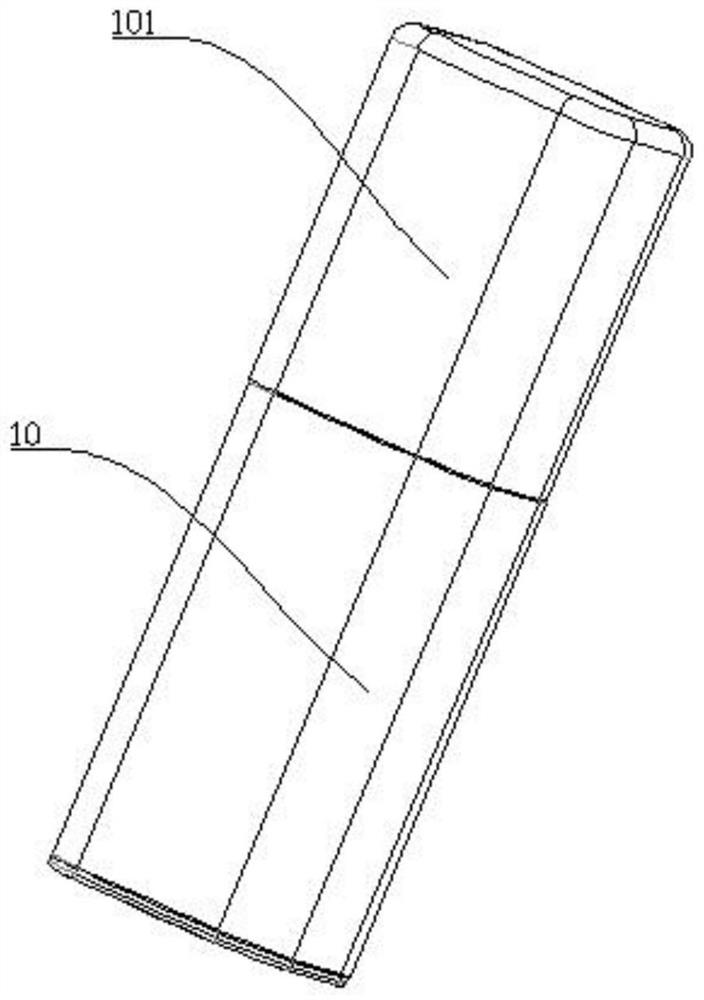
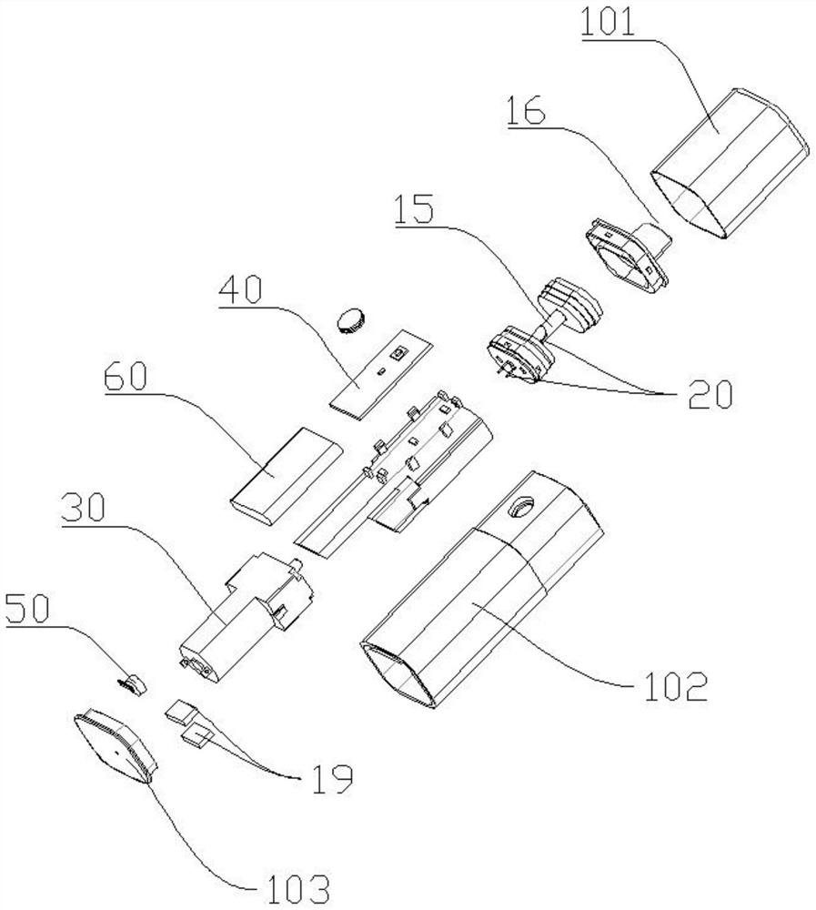
[0049] This embodiment provides a method for generating aerosol by using an aerosol generating device.

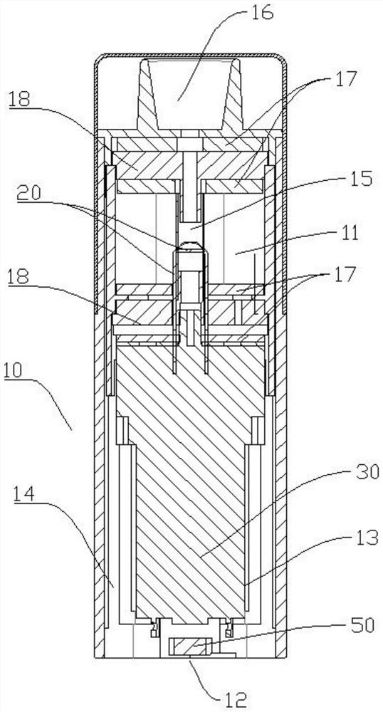
[0050] Such as Figure 1~4 Shown is the aerosol generating device in this embodiment, including a housing 10 , a heating device 20 , an air supply device 30 , a first control device 40 and a second control device 50 . The casing 10 includes a middle shell 102 and a lower cover 103 arranged at the bottom of the middle shell 102 for sealing the middle shell 102; a cavity 11 for accommodating the aerosol generating matrix is ​​formed in the middle shell 102. In this embodiment, the middle shell 102 is provided with sealing blocks 18 arranged at intervals along the gas flow direction, and the sealing blocks 18 are in contact with the inner wall of the middle shell 102 to seal, so that a cavity 11 is formed between the sealing block 18 and the middle shell 102. In this embodiment, the sealing blocks 18 are Silicone material. Both the bottom and the top of the sealing block 18 ...

Embodiment 2

[0069] This embodiment provides a method for producing an aerosol using an aerosol generating device, the aerosol generating device in this embodiment is as Figure 5 As shown, the aerosol generating device in this embodiment is based on the addition of a gas purification device 70 on the basis of Embodiment 1, and the gas purification device 70 is arranged in the middle shell 102 for purifying the gas entering the middle shell 102 . In this embodiment, the gas purification device 70 is arranged between the cavity 11 and the gas supply device 30, the gas inlet end of the gas purification device 70 communicates with the first airflow passage 13 and the second airflow passage 14 respectively, and the gas outlet connects with the mixing The airflow channel 15 is connected, so that the gas coming out of the first airflow channel 13 and the second airflow channel 14 can be purified to ensure a more hygienic aerosol. In practical applications, the purification device 70 can also be...


PUM


Abstract

The invention discloses an aerosol generating method, relating to the technical field of aerosol production. The method comprises the following steps: S1, a user sucks through a mist outlet, outside air enters an aerosol generating device, the aerosol generating device automatically detects the flow or / and air pressure of the entering air, and when the flow or / and air pressure of the entering airis / are larger than a preset threshold value of the aerosol generating device, the aerosol generating device automatically controls a heating device to be started; or / and, the user starts an air supplydevice and the heating device, and the air supply device introduces air into the aerosol generating device; and S2, the heating device heats and atomizes an aerosol generating substrate in the aerosol generating device, and the atomized aerosol is mixed with external air or / and gas to form aerosol. According to the aerosol generating method, the aerosol can be generated in a suction mode, a userdoes not need to suck the aerosol, the aerosol generating device is used for automatically generating the aerosol, and the user can select different working modes according to requirements.

Description

technical field [0001] The invention relates to the technical field of aerosol production, in particular to an aerosol production method. Background technique [0002] As people pay more and more attention to their health and environmental safety, people realize that tobacco is very harmful to people's health. Therefore, a product called "electronic cigarette" has been produced. [0003] Electronic cigarettes are also known as virtual cigarettes and electronic atomizers. It is a relatively common imitation cigarette electronic product, which mainly generates "smoke" by atomizing e-liquid. Compared with traditional cigarettes, electronic cigarettes have similar appearance and taste, and are even more expensive than ordinary traditional cigarettes. more flavors. However, e-cigarette liquid or e-liquid does not contain harmful substances such as nicotine or tar. When cigarette consumers smoke this kind of e-cigarette, they can avoid the intake of harmful substances, and can s...

Claims


Application Information

Patent Timeline
IPC IPC(8): A24F40/46A24F40/48A24F40/50A24F40/40A24F40/10
CPCA24F40/10A24F40/40A24F40/46A24F40/48A24F40/50
Inventor 于亮张亮盛林
Owner 北京翔越科技有限公司
Why Eureka
Try Eureka