Rocket turbopump floating ring seal testing testbed
A rocket turbine and sealing test technology, which is applied to rocket engine devices, pump control, non-variable pumps, etc., can solve the problems of flow-induced vibration instability, increased rotor vibration, low stability and reliability of rocket engines, etc.
- Summary
- Abstract
- Description
- Claims
- Application Information
AI Technical Summary
Problems solved by technology
Method used
Image
Examples
specific Embodiment approach 1
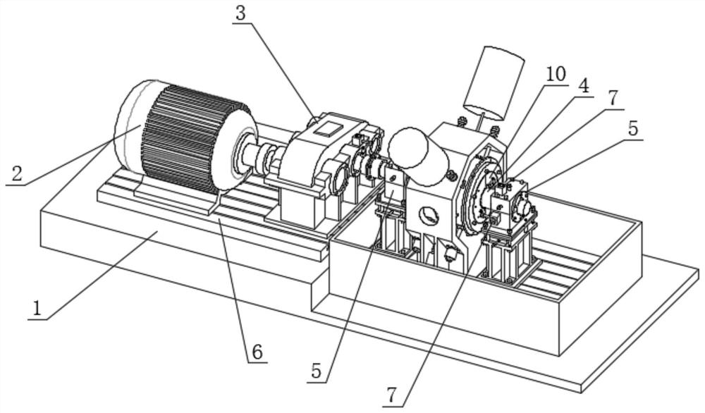
[0023] Specific implementation one: as Figures 1 to 4 As shown, the rocket turbo pump floating ring seal test bench of this embodiment includes a test base platform 1, a servo motor 2, a variable speed gearbox 3, a rotor 4, a test bench body, a T-slot guide 6, two bearing seats 5, Two positioning rings 13 and a plurality of eddy current displacement sensors 7; two T-slot guide rails 6 are arranged in sequence along the length direction of the test foundation platform 1, and the servo motor 2 and the variable speed gearbox 3 are arranged on the T-slot guide rail 6 in sequence, The rotor 4 is installed on the T-slot guide rail 6 through two bearing seats 5, and the output shaft of the servo motor 2 is connected with the rotor 4 through the transmission gearbox 3 and the coupling; the test bench body includes a front cavity 8 and a middle cavity 9. , the rear cavity 10 and two cavity labyrinth seals, both ends of the test bench body are provided with a positioning ring 13 and a ...
specific Embodiment approach 2
[0024] Specific implementation two: as figure 1 and image 3 As shown, in this embodiment, the front cavity 8 , the middle cavity 9 and the rear cavity 10 are fixedly connected together by a plurality of through bolts, and the two adjacent cavities are sealed by a sealing end face gasket.
[0025] In this way, the sealing between the two adjacent cavities is sealed by the sealing end face gasket, and the sealing between the front cavity 8, the middle cavity 9 and the rear cavity 10 is realized. At the same time, the front cavity 8 and the middle cavity 9 are sealed. The detachable connection with the rear cavity 10 realizes the installation and removal of the floating ring.
[0026] Other components and connection relationships are the same as in the first embodiment.
specific Embodiment approach 3
[0027] Specific implementation three: as figure 1 and figure 2 As shown, the T-slot guide 6 in this embodiment is composed of a first T-slot guide and a second T-slot guide. The first T-slot guide and the second T-slot guide are machined with a plurality of T-slots along their lengths. The groove, the servo motor 2 and the gear box 3 are installed on the upper end surface of the first T-slot guide rail, and the rotor 4, the test bench body and the two bearing seats 5 are installed on the upper end surface of the second T-slot guide rail.
[0028] This design facilitates adjusting the position of the servo motor 2 and the transmission gearbox 3 on the first T-slot guide rail, and facilitates adjusting the position of the rotor 4, the test bench body and the two bearing seats 5 on the second T-slot guide rail.
[0029] Other compositions and connection relationships are the same as in the first or second embodiment.
PUM
 Abstract
Description
Claims
Application Information
 - Generate Ideas
- Intellectual Property
- Life Sciences
- Materials
- Tech Scout
- Unparalleled Data Quality
- Higher Quality Content
- 60% Fewer Hallucinations
Browse by: Latest US Patents, China's latest patents, Technical Efficacy Thesaurus, Application Domain, Technology Topic, Popular Technical Reports.
© 2025 PatSnap. All rights reserved.Legal|Privacy policy|Modern Slavery Act Transparency Statement|Sitemap|About US| Contact US: help@patsnap.com


