
Deslagging automatic water drainer for negative-pressure gas pipeline

An automatic water release and gas pipeline technology, which is applied in the directions of drainage, gas discharge, chemical instruments and methods, etc., can solve the problems of slow rise of water level, sedimentation of drilling slag, and inability to work normally, and achieves powerful and accurate opening and closing. , the effect of rapid action

Pending Publication Date: 2020-09-08
重庆能投渝新能源有限公司
View PDF0 Cites 0 Cited by
  • Summary
  • Abstract
  • Description
  • Claims
  • Application Information

AI Technical Summary

Problems solved by technology

Manual water discharge and slag removal is time-consuming and inefficient
The existing automatic water discharge devices are all barrel-shaped, with a floating ball linkage mechanism inside. During use, the water level in the bucket often rises slowly, the push-pull force is insufficient, and the drilling slag is deposited, resulting in failure to work normally. The bucket cannot clean up the slag

Method used


Image

  • Deslagging automatic water drainer for negative-pressure gas pipeline
  • Deslagging automatic water drainer for negative-pressure gas pipeline

Examples


Embodiment Construction

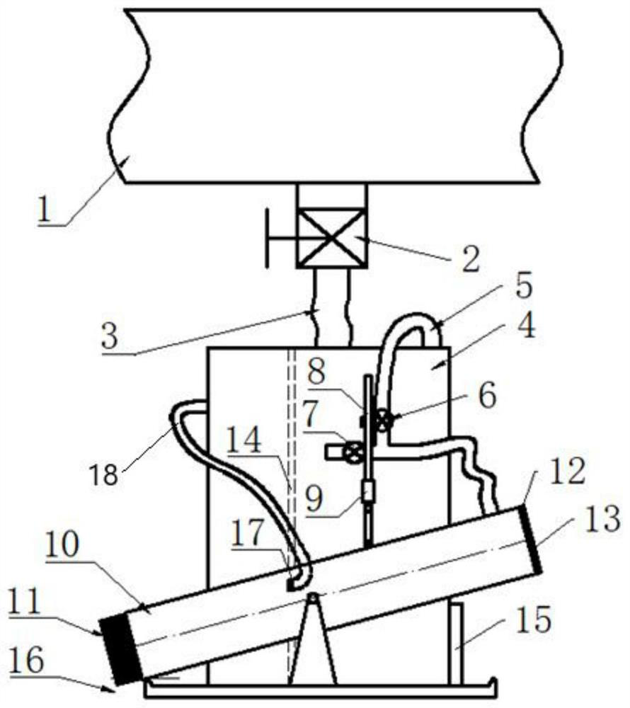
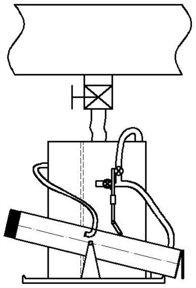
[0022] join figure 1 , figure 2 , a negative pressure gas pipeline slag removal automatic water drainer, comprising a base 16, water and sediment bucket 4, water tank 10 for draining.

[0023] Said accumulated water discharge bucket 10 is provided with an inclination, a counterweight 11 is arranged at the sealing end of said accumulated water discharge bucket 10, and a movable cover 13 is arranged at the open end of the accumulated water discharge bucket 10, and the upper end of said movable cover 13 is in contact with the accumulated water. The open end of water bucket 10 is hinged, and the lower end of movable cover plate 13 is free end, and described movable cover plate 13 is provided with sealing ring 12, is used for sealing the open end of accumulated water water bucket 10. The middle and lower part of the accumulated water bucket 10 is hingedly supported by the support, and the accumulated water sediment bucket 4 and the support are all installed on the base. When the...


PUM


Abstract

The invention discloses a deslagging automatic water drainer for a negative-pressure gas pipeline. The deslagging automatic water drainer is large in push-pull force, and comprises an accumulated water sediment barrel and an accumulated water discharge barrel, wherein a counterweight is arranged at the sealed end of the accumulated water discharge barrel, a movable cover plate is arranged at the open end of the accumulated water discharge barrel, and the middle lower part of the accumulated water discharge barrel is hinged and supported through a support; a slag blocking filter plate is vertically arranged in the accumulated water sediment barrel and divides the accumulated water sediment barrel into a slag storage chamber and a water storage chamber, a water inlet pipe and an air passinghose are connected to the upper portion of the slag storage chamber, the air passing hose is connected with the open end of the accumulated water drainage barrel, and a drainage hose is connected between the water storage chamber and the accumulated water drainage barrel; a first air valve is arranged on the air passing hose, a branch pipe is in T connection to the air passing hose, a second air valve is arranged on the branch pipe, and transmission gears are arranged on valve rods of the first air valve and the second air valve; and a push-pull rod is in sliding fit with the barrel wall of the accumulated water sediment barrel, a connecting rod is hinged to the lower end of the push-pull rod, the lower end of the connecting rod is hinged to the accumulated water drainage barrel, and the push-pull rod meshes with transmission gears on the first air valve and the second air valve simultaneously.

Description

technical field [0001] The invention relates to the technical field, in particular to an automatic water release device for removing slag in a negative pressure gas transmission pipeline. Background technique [0002] Gas drainage pipe network needs to be laid underground in coal mines. The extracted gas is often accompanied by impurities such as water, coal slag, and rust, which must be removed in time to ensure the normal operation of the drainage system. Manual water discharge and slag removal is time-consuming and inefficient. The existing automatic water discharge devices are all barrel-shaped, with a floating ball linkage mechanism inside. During use, the water level in the bucket often rises slowly, the push-pull force is insufficient, and the drilling slag is deposited, resulting in failure to work normally. Buckets cannot clean up accumulated slag. Contents of the invention [0003] The object of the present invention is to overcome the deficiencies of the prior...

Claims


Application Information

Patent Timeline
IPC IPC(8): E21F16/00E21F7/00B01D29/03
CPCB01D29/03E21F7/00E21F16/00
Inventor 任梅青刘朝富黄勇吴斌王伟
Owner 重庆能投渝新能源有限公司
Learn More