
Goaf air leakage prevention method for thin coal seam N00 mining method

A goaf and anti-air leakage technology, which is applied in mining equipment, ground mining, mining equipment, etc., can solve problems such as aggravating the degree of air leakage in the goaf, insufficient air volume at the working face, and increased risk of spontaneous combustion of leftover coal.

Active Publication Date: 2020-09-08
BEIJING ZHONGKUANG INNOVATION ALLIANCE ENERGY & ENVIRONMENTAL SCI RES INST
View PDF8 Cites 3 Cited by
  • Summary
  • Abstract
  • Description
  • Claims
  • Application Information

AI Technical Summary

Problems solved by technology

However, for this method of coal mining, the working face is arranged in the way of pulling the working face, which belongs to the forward mining method, and the ventilation method is "U-shaped". The roadway wall is composed of gangue filling. One side of the roadway is reserved as the air inlet roadway, and the other side of the roadway is reserved as the air return roadway. Since the extraction ventilation system is mostly used in the mine, the air pressure in the return air roadway is lower than that of the air inlet roadway. The air pressure in the air tunnel will be significantly lower than the air pressure on the working face. Under the action of the air pressure difference, the air flow in the air inlet roadway and the air flow in the working face will easily flow through the goaf and escape, which will aggravate the degree of air leakage in the goaf, resulting in the loss of The risk of spontaneous combustion of coal increases. At the same time, the escaping air flow carries toxic and harmful gases in the goaf, causing the concentration of toxic and harmful gases in the return air lane to exceed the limit. In addition, air leakage easily leads to insufficient air volume at the working face

Method used


Image

  • Goaf air leakage prevention method for thin coal seam N00 mining method
  • Goaf air leakage prevention method for thin coal seam N00 mining method
  • Goaf air leakage prevention method for thin coal seam N00 mining method

Examples


Embodiment Construction

[0030] Example embodiments will now be described more fully with reference to the accompanying drawings. However, the example embodiments can be implemented in various forms, and should not be construed as being limited to the embodiments set forth herein; on the contrary, these embodiments are provided so that this disclosure will be comprehensive and complete, and fully convey the concept of the example embodiments To those skilled in the art. The same reference numerals in the figures represent the same or similar structures, and thus their detailed descriptions will be omitted.

[0031] Although relative terms such as "upper" and "lower" are used in this specification to describe the relative relationship between one component of an icon and another component, these terms are used in this specification only for convenience, for example, according to the drawings. The direction of the example described. It can be understood that if the device of the icon is turned over and t...


PUM


Abstract

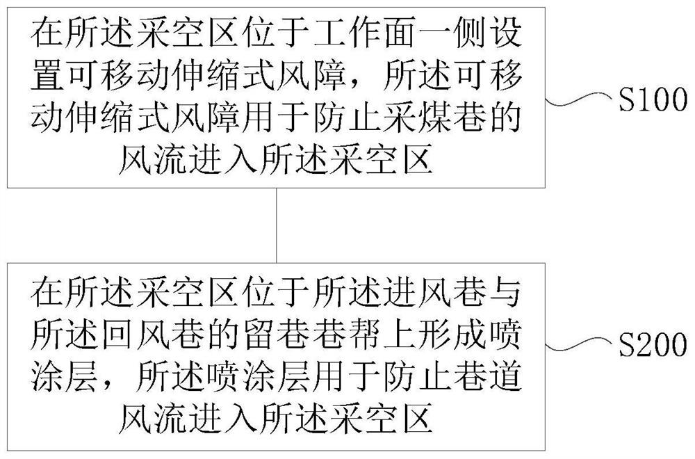
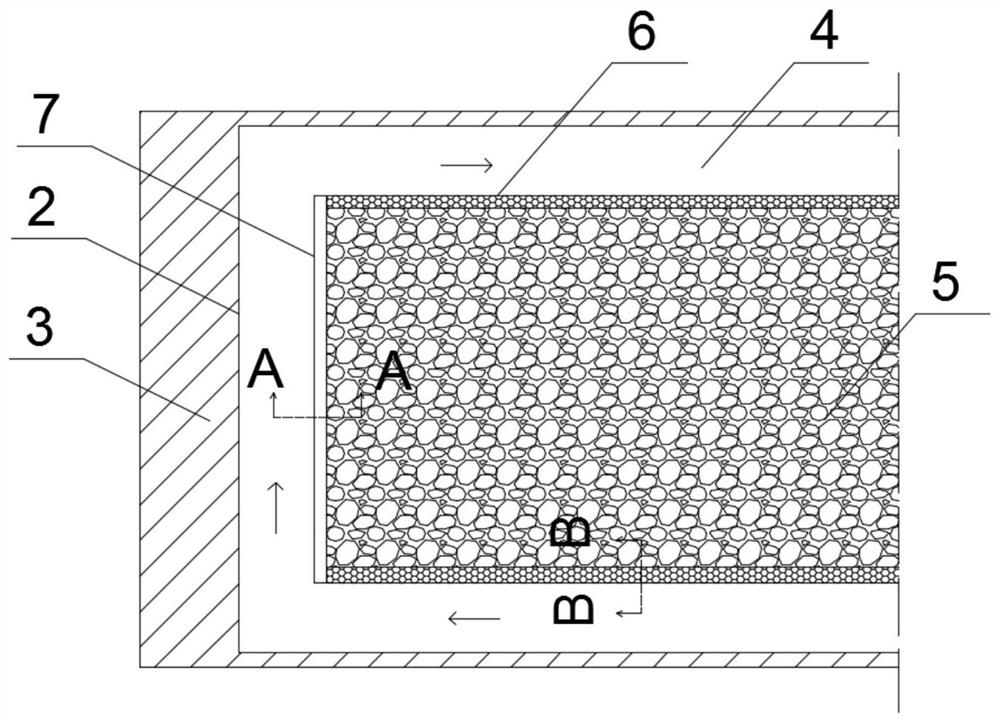
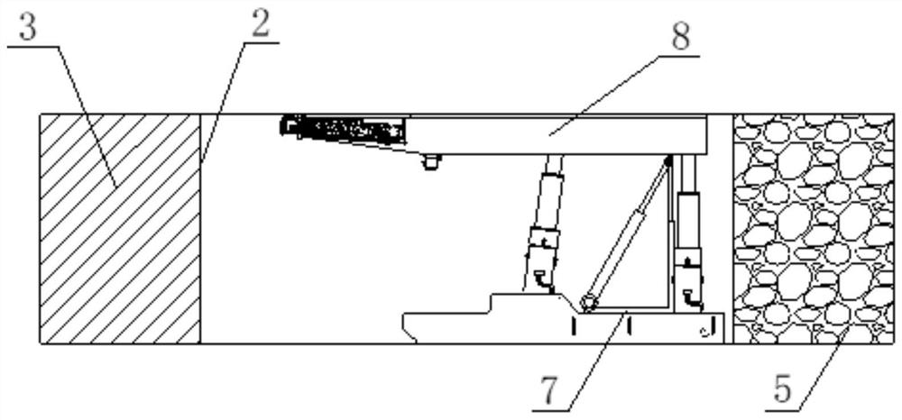
The invention relates to a goaf air leakage prevention method for a thin coal seam N00 mining method. An air inlet roadway and an air return roadway are formed on the two sides of a goaf. The goaf airleakage prevention method comprises the steps that a movable telescopic air barrier is arranged on one side, positioned at a working surface, of the goaf, wherein the movable telescopic air barrier is used for preventing airflow of a coal mining roadway from entering the goaf; and spraying layers are formed on the goaf on the sides of retaining roadways of the air inlet roadway and the air returnroadway, wherein the spraying layers are used for preventing the airflow of the roadways from entering the goaf. According to the goaf air leakage prevention method for the thin coal seam N00 miningmethod, the movable telescopic air barrier capable of preventing the air leakage of the working surface is arranged between the goaf and the working surface, so that the airflow of the working surfaceis prevented from entering the goaf; and spraying materials are uniformly sprayed to form the spraying layers on the sides of the retaining roadways formed by continuously formed gangue filling supports, so that the airflow of the roadways is prevented from entering the goaf, and the tightness of goaf at the roadway sides is guaranteed.

Description

Technical field [0001] The present disclosure relates to the technical field of mineral mining, and in particular, to a method for preventing air leakage in a goaf used for a thin coal seam N00 mining method. Background technique [0002] For a long time, thin coal seam mining has been affected by the mining environment, and there are problems such as difficult mining, narrow mining space, low mining height, low coal recovery rate, and equipment and personnel unable to work normally in this operating environment. In recent years, with the gradual maturity of medium-thick and thick coal seam resource mining technology, the research and development of thin coal seam mining technology and equipment is urgent. [0003] At present, thin coal seams are mined using the high-grade general mining double-drawing face N00 method, that is, no tunneling and no pillar mining technology is required. This method can reduce costs, improve profits and work efficiency. However, for this mining metho...

Claims


Application Information

Patent Timeline
IPC IPC(8): E21C41/18E21F17/107E21F17/103
CPCE21C41/18E21F17/103E21F17/107
Inventor 何满潮王亚军明灿杨刚刘简宁
Owner BEIJING ZHONGKUANG INNOVATION ALLIANCE ENERGY & ENVIRONMENTAL SCI RES INST
Learn More