Automatic roller replacing equipment for producing composite flow medium

A diversion net, automatic technology, applied in the field of composite diversion net, can solve the problems of manual cutting and replacement, low work efficiency, and inability to realize the continuity of the production line, so as to ensure continuous winding work and improve work efficiency , the effect of saving working time

Inactive Publication Date: 2020-09-08
潘利斌
View PDF0 Cites 2 Cited by
  • Summary
  • Abstract
  • Description
  • Claims
  • Application Information

AI Technical Summary

Problems solved by technology

[0005] The purpose of the present invention is to address the deficiencies of the prior art. By setting a new winding roller element to cooperate with the winding mechanism, the clamping of the composite flow guide net is completed at the station to be replaced, and then the cutting mechanism is used to cut Completing the automatic separation of the composite deflector net on the new winding roller element and the old winding roller element, and then through the switching mechanism, the station switching work of the new winding roller element and the old winding roller element is realized, and then completed The automatic replacement of new winding roller elements and old winding roller elements solves the problem of manual cutting and replacement of new winding rollers when the winding roller completes the winding work on the composite flow guide net, which leads to low work efficiency , the technical problem that the continuity of the production line cannot be realized

Method used


Image

  • Automatic roller replacing equipment for producing composite flow medium
  • Automatic roller replacing equipment for producing composite flow medium
  • Automatic roller replacing equipment for producing composite flow medium

Examples


Embodiment 1

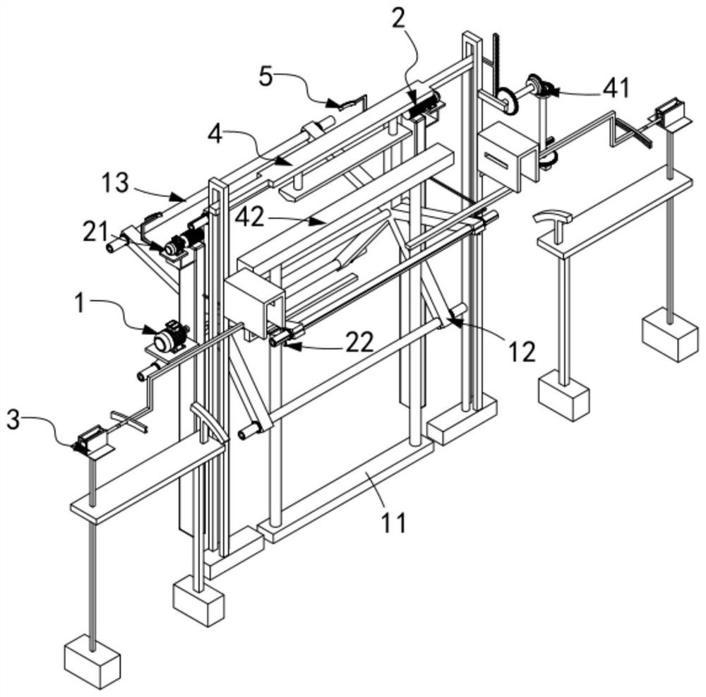
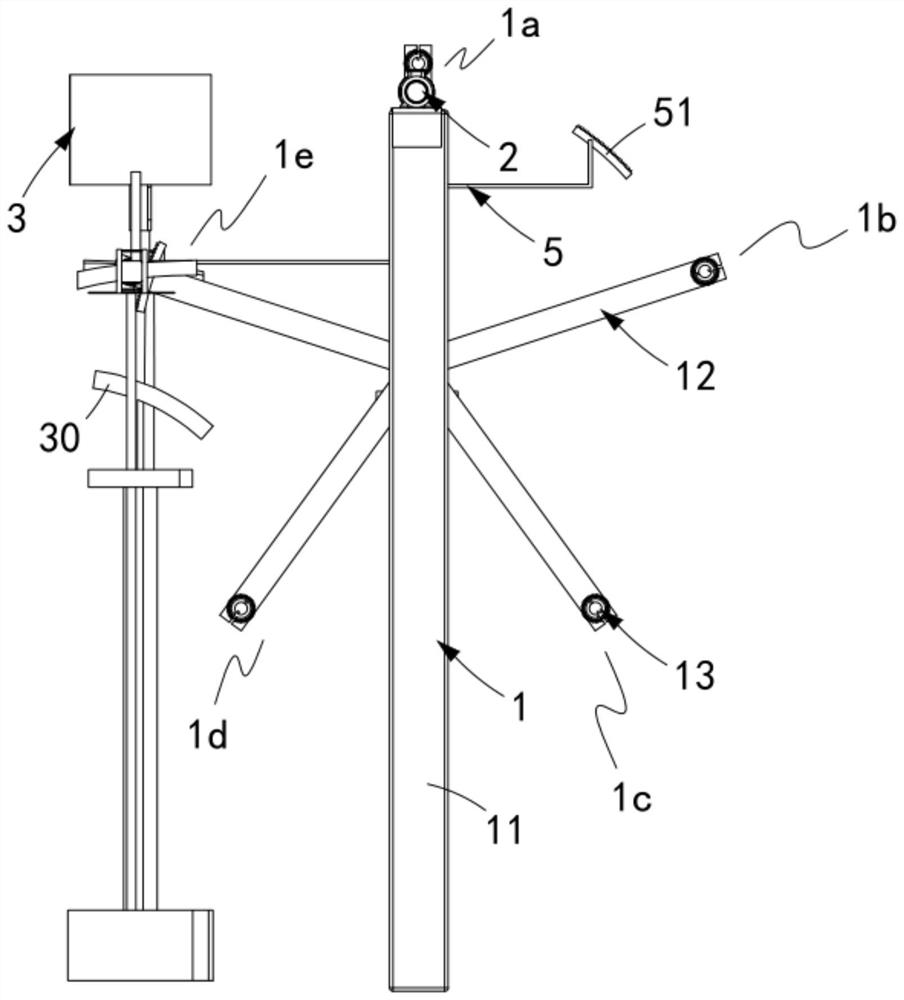
[0070] Such as figure 1 , figure 2 As shown, an automatic roll changing equipment for composite guide net production, including:

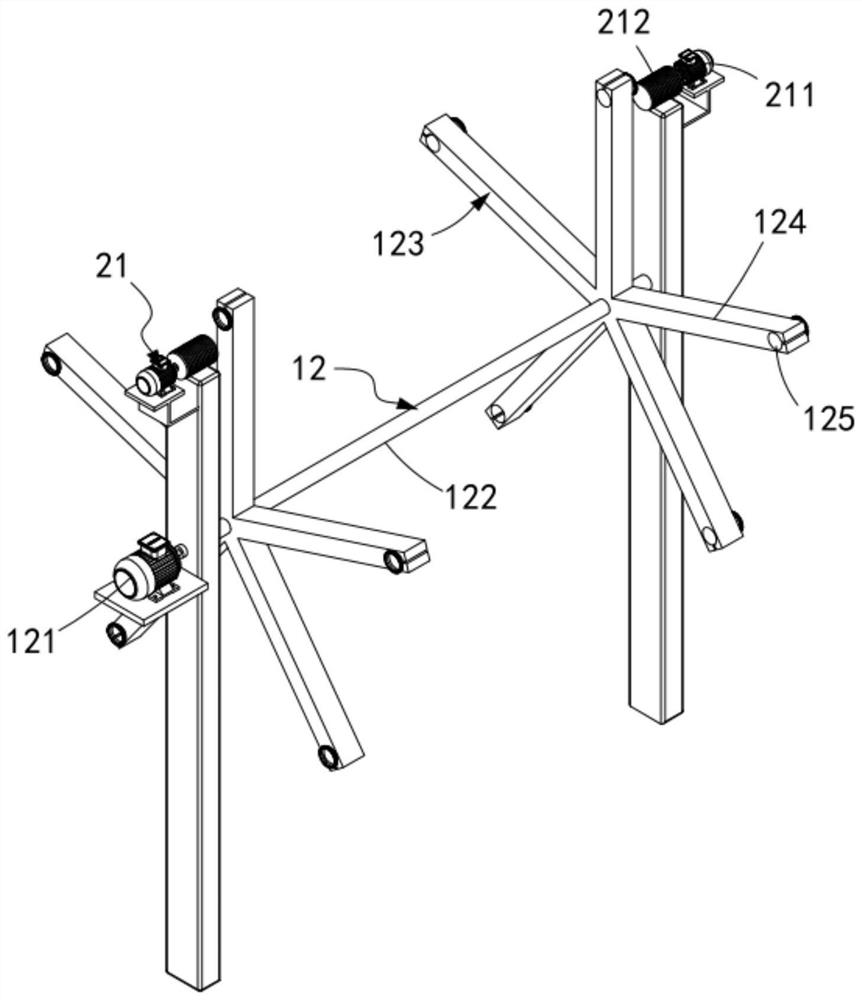
[0071] Switching mechanism 1, the switching mechanism 1 includes a frame 11, a revolving assembly 12 rotatably arranged on the frame 11, and a take-up roller element 13 rotatably arranged on the revolving assembly 12, the revolving assembly 12 along In the circumferential direction, there are winding station 1a, packing station 1b, output station 1c, upper roller station 1d and station to be replaced 1e;

[0072] The driving mechanism 2, the driving mechanism 2 includes an active assembly 21 arranged on the winding station 1a and used to drive the winding roller element 13 to perform a circular rotation to complete the winding work and installed on the frame 11 and a first autorotation assembly 22 for driving the winding roller element 13 to autorotate;

[0073] The winding mechanism 3, the winding mechanism 3 is provided with two groups and sy...

Embodiment 2

[0121] Such as figure 2 As shown, the components that are the same as or corresponding to those in the first embodiment are marked with the corresponding reference numerals in the first embodiment. For the sake of simplicity, only the differences from the first embodiment will be described below. The difference between this embodiment two and embodiment one is:

[0122] further, such as figure 2 As shown, the sealing mechanism 5 includes a second arc-shaped rack 51, the second arc-shaped rack 51 is provided in two groups and is arranged in one-to-one correspondence with the driving gear 221, the second arc-shaped rack 51 is arranged along the rotation direction of the epicyclic assembly 12 and meshed with the driving gear 221 .

[0123] What is worth mentioning here is that by setting the second arc-shaped rack 51, the winding roller element 13 after finishing the winding work is in the process of revolving, and the winding roller element 13 carries out Automatic winding ...


PUM


Abstract

The invention relates to automatic roller replacing equipment for producing a composite flow medium. The automatic roller replacing equipment comprises a switching mechanism, a driving mechanism, twowinding mechanisms, a cutting mechanism and a sealing mechanism, wherein the switching mechanism comprises a rack, a turnover assembly and a winding roller element; the driving mechanism comprises driving assemblies and a first rotation assembly; the two winding mechanisms are symmetrically arranged on the two sides of the winding roller element and are matched with the winding roller element to finish clamping work on a finished product; the cutting mechanism is arranged between a station to be replaced and a winding station and comprises a transmission assembly and a cutter assembly; the sealing mechanism is used for automatically carrying out finishing work on a composite glow medium tail after being cut on the winding roller element; and the sealing mechanism is positioned on a packaging station. The automatic roller replacing equipment for producing the composite flow medium solves the technical problems that cutting and new winding roller replacement need to be completed manuallywhen a winding roller completes the winding of the composite flow medium, so that the working efficiency is low, and the continuity of a production line is not achieved.

Description

technical field [0001] The invention relates to the technical field of composite flow guide nets, in particular to an automatic roll changing device for the production of composite flow guide nets. Background technique [0002] Several auxiliary materials need to be used in the production of vacuum infusion process, including release cloth, diversion net, porous film, vacuum bag film and so on. During production, the auxiliary materials are laid layer by layer on the main material. The porous film is very thin and soft, and can be naturally laid flat on gentle parts, but when the mold has a relatively steep "U"-shaped interface, the laid The porous membrane will fall off. In order to ensure that the porous membrane does not fall off, the existing production process is to spray glue on the surface of the original material, stick the porous membrane to the composite material, and then lay the diversion net. Sometimes, in some steep places, the diversion net will still fall of...

Claims


Application Information

Patent Timeline
Patent Type & Authority Applications(China)
IPC IPC(8): B65H19/30B65H19/26B65H19/28B26D7/32B26D5/08B26D1/08B65B17/00
CPCB26D1/085B26D5/083B26D7/32B65B17/00B65H19/26B65H19/28B65H19/305B65H2701/19
Inventor 潘利斌
Owner 潘利斌
Why Eureka
Try Eureka