A stroke control mechanism of a catenary conveying device

A conveying device and stroke control technology, which is applied in the field of stroke control mechanism, can solve problems such as mechanical fatigue of contact springs, easy jamming of rotating parts, and inaccurate positioning of hooks, so as to reduce inaccurate positioning, avoid bump damage, and reduce failures rate effect

Active Publication Date: 2021-08-10
ANHUI HELI CO LTD
View PDF10 Cites 0 Cited by
  • Summary
  • Abstract
  • Description
  • Claims
  • Application Information

AI Technical Summary

Problems solved by technology

[0004] The object of the present invention is to provide a stroke control mechanism of a catenary conveying device. A driven wheel is arranged in the catenary conveying assembly; a movable plate is arranged above the driven wheel, and a proximity switch is installed in the movable plate, which solves the problem of the existing shot blasting. The position limit of the machine catenary casting hook adopts a mechanical travel switch, the rotating part is easy to get stuck and does not rebound, and the mechanical fatigue of the contact spring in the travel switch causes the hook to be inaccurately positioned, frequent failures, and often need to be replaced.

Method used


Image

  • A stroke control mechanism of a catenary conveying device
  • A stroke control mechanism of a catenary conveying device
  • A stroke control mechanism of a catenary conveying device

Examples


Embodiment Construction

[0027] The following will clearly and completely describe the technical solutions in the embodiments of the present invention with reference to the accompanying drawings in the embodiments of the present invention. Obviously, the described embodiments are only some, not all, embodiments of the present invention. Based on the embodiments of the present invention, all other embodiments obtained by persons of ordinary skill in the art without creative efforts fall within the protection scope of the present invention.

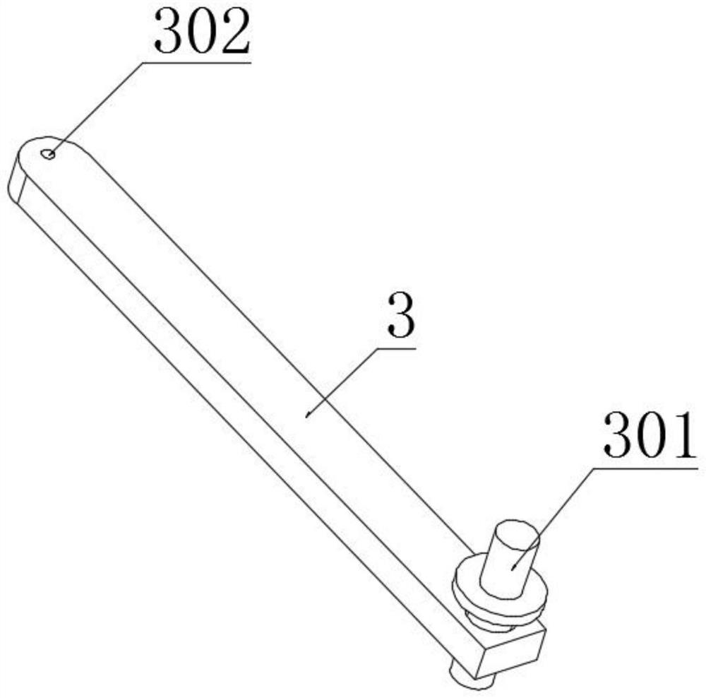
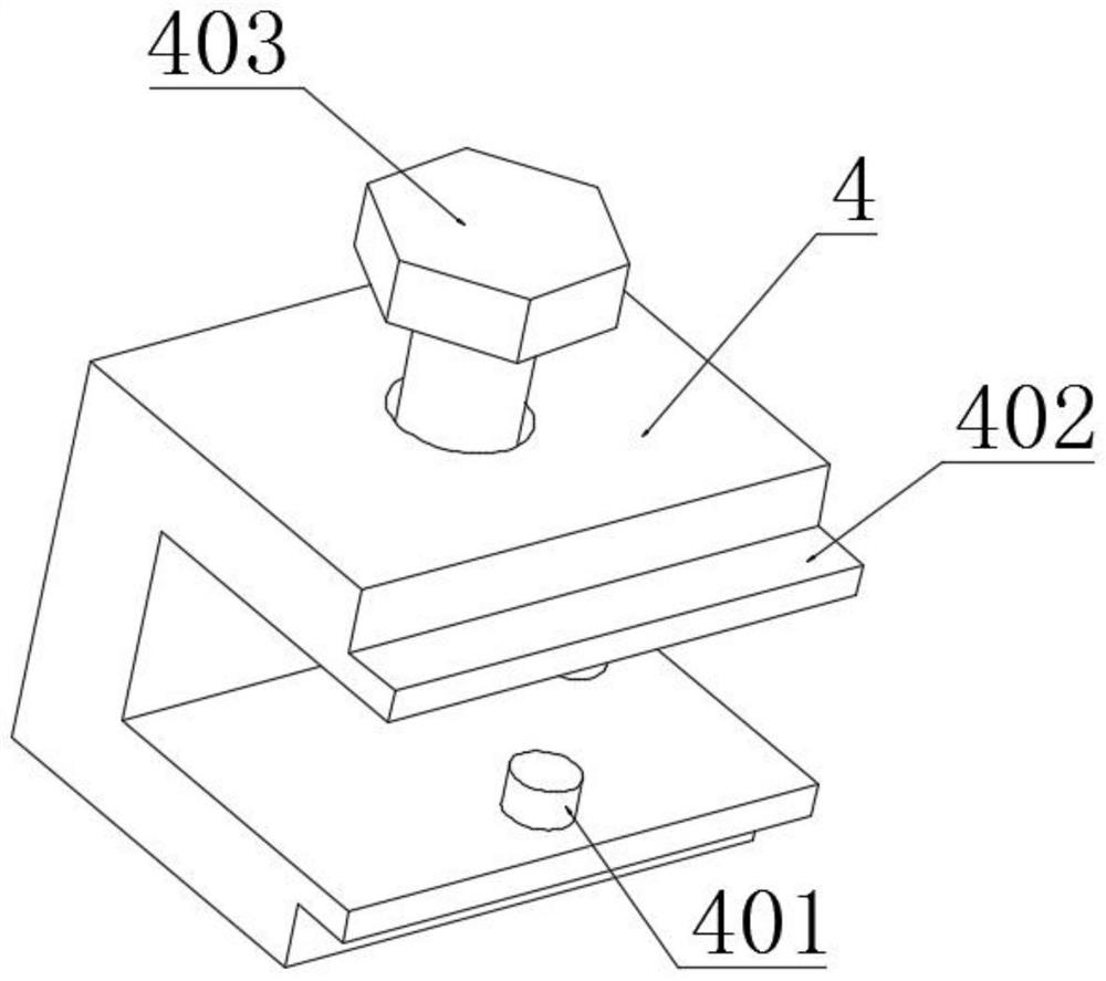
[0028] see Figure 1-5 As shown, the present invention is a stroke control mechanism of a catenary conveying device, comprising a catenary conveying assembly 1; the catenary conveying assembly 1 is arranged on a suspended chain conveyor; a driven wheel 2 is arranged in the catenary conveying assembly 1; the driven wheel 2 is provided with a movable plate 3; one side of the driven wheel 2 is provided with a tripod to achieve signal transmission and avoid damage to t...


PUM


Abstract

The invention discloses a stroke control mechanism of a catenary conveying device and relates to the technical field of catenary conveying. The invention comprises a catenary conveying assembly; the catenary conveying assembly is arranged on a suspension chain conveyor; a driven wheel is arranged in the catenary conveying assembly; a movable plate is arranged above the driven wheel; a tripod is arranged on one side of the driven wheel; There are three strip-shaped plates in a circumferential array on the outer side of the circular plate; a proximity switch is installed in the movable plate; a slider is movably connected to the movable plate; the slider is slidably connected in the chute; a fixed frame is matched in the chute. In the present invention, a driven wheel is provided in the catenary conveying assembly; a movable plate is arranged above the driven wheel, and a proximity switch is installed in the movable plate, which can minimize the inaccurate positioning of the hook, reduce the failure of the shot blasting machine, and facilitate the adjustment of the position of the proximity switch , so as to control the stroke of the conveying system.

Description

technical field [0001] The invention belongs to the technical field of catenary conveying, in particular to a stroke control mechanism of a catenary conveying device. Background technique [0002] Shot blasting machine refers to the casting equipment that uses the high-speed projectile thrown by the shot blaster to clean or strengthen the surface of the casting. Core and clean up. Shot blasting machines are faster and more effective than other surface treatment techniques and can be used for part retention or stamping after the casting process. In the actual processing process, the speed limit of the catenary of the shot blasting machine is generally set above the catenary. Due to the swing of the catenary, the limit is often hung and collided, causing the line to stop for maintenance and delaying the shot blasting efficiency. In addition, the position limit of the catenary casting hook of the traditional shot blasting machine adopts a mechanical travel switch, the rotatin...

Claims


Application Information

Patent Timeline
Patent Type & Authority Patents(China)
IPC IPC(8): B65G17/20B65G17/30
CPCB65G17/20B65G17/30
Inventor 吴友坤孙启圣谭震陈元生
Owner ANHUI HELI CO LTD
Why Eureka
Try Eureka