
Small large-resistance buffer

A buffer and resistance technology, applied in the field of small and large resistance buffers, can solve the problems of high resistance value products, increase the reverse rebound resistance of the piston rod, and high requirements for small hole processing, and solve the problem of large resistance value products. , easy to control and guaranteed effect

Pending Publication Date: 2020-09-04
GANZHOU HEYING AUTO PARTS
View PDF0 Cites 0 Cited by
  • Summary
  • Abstract
  • Description
  • Claims
  • Application Information

AI Technical Summary

Problems solved by technology

[0002] In the existing buffer structure, due to the small outer diameter of the product piston and the small oil hole under certain circumstances, it is necessary to increase the fluid viscosity value to increase the resistance value of the buffer product, but it also increases the reverse rebound of the piston rod The resistance and spring force are limited by the size of the product, resulting in a slow reset speed of the buffer piston rod, which affects the use effect. Because the resistance of the buffer product is determined by the diameter of the oil hole and the outer diameter of the piston, the small size buffer corresponds to The size of the shell cavity is small, and it is difficult to produce products with high resistance value. Only small-sized oil holes can be used to meet the requirements of large resistance values, and the shock absorbers with small oil holes have very high requirements for small hole processing and very strict molding processing. , requires precision machining, which consumes a lot of manpower and material resources

Method used


Image

  • Small large-resistance buffer
  • Small large-resistance buffer
  • Small large-resistance buffer

Examples


Embodiment 1

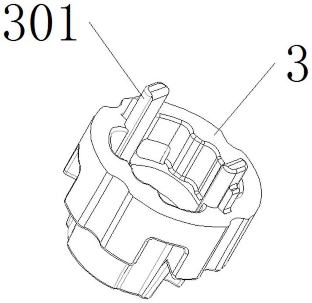
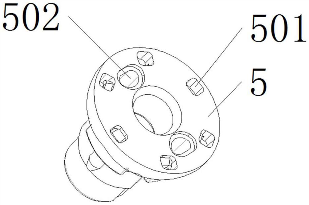
[0033] When the piston 5 is pressed down by an external force, the O-ring 4 is stuck to the inner wall of the housing 1 and remains still, and at the same time, the damping oil layer 9 in the B chamber pushes the O-ring 4 to align with the lower plane of the piston 5 through the groove of the seat cover 3, Close the convective through hole 501 on the piston 5, so that the damping oil layer 9 in the B chamber completely passes through the small oil hole formed by the protruding shaft 301 and the through hole 501. The small cross-sectional area of ​​the oil hole makes the damping oil layer between the A and B chambers 9 The hydraulic pressure difference is large, and the stroke has a large reverse resistance effect.

Embodiment 2

[0035] When the piston 5 is under the action of the elastic force of the spring 2, it produces a rebound and reset action, and the damping oil layer 9 in the A chamber flows through the convection hole 502 on the piston 5, and the O-ring 4 is squeezed to move down, completely opening the damping of the A chamber and the B chamber. The convection channel composed of the protruding shaft 301 and the through hole 501 in the oil layer 9 has a large cross-sectional area, so that the hydraulic pressure difference of the damping oil layer 9 between the A and B rooms is small, and the reverse resistance value is small. Under the action of elastic force, the piston 5 can be reset to the original position at the top.


PUM


Abstract

The invention provides a small large-resistance buffer which comprises a shell and a spring; the spring is embedded into the shell; a seat sleeve is arranged on the right side of the spring; a pistonis embedded into the right side of the seat sleeve; an O-shaped ring is embedded between the seat sleeve and the piston; a piston rod is embedded into the right side of the seat sleeve; a pressure accumulation sponge assembly is embedded into the outer surface of the piston rod; a Y-shaped ring assembly is fixedly connected to the right side of the pressure accumulation sponge assembly; and a damping oil layer is filled in the shell. For the small large-resistance buffer, an oil passing small hole is divided into seat sleeve convex shafts and a matching interval between piston through holes, the sizes of the convex shafts and the through holes are far larger than that of the small hole, the forming and manufacturing process is easy to control and guarantee, and the problem that a small-sized buffer is difficult to produce a large resistance value product is solved.

Description

technical field [0001] The invention relates to the technical field of dampers, in particular to a small-sized high-resistance buffer. Background technique [0002] In the existing buffer structure, due to the small outer diameter of the product piston and the small oil hole under certain circumstances, it is necessary to increase the fluid viscosity value to increase the resistance value of the buffer product, but it also increases the reverse rebound of the piston rod The resistance and spring force are limited by the size of the product, resulting in a slow reset speed of the buffer piston rod, which affects the use effect. Because the resistance of the buffer product is determined by the diameter of the oil hole and the outer diameter of the piston, the small size buffer corresponds to The size of the shell cavity is small, and it is difficult to produce products with high resistance value. Only small-sized oil holes can be used to meet the requirements of large resistan...

Claims


Application Information

Patent Timeline
IPC IPC(8): F16F9/18F16F9/32
CPCF16F9/18F16F9/3214
Inventor 王盛
Owner GANZHOU HEYING AUTO PARTS
Learn More