Formwork reinforcement device for building
A technology for formwork reinforcement and construction. It is applied in the field of formwork reinforcement equipment. It can solve the problems of mold running and uneven force applied to reinforcement plates, and achieve the effects of uniform force application, simple and orderly reinforcement process, and uniform force.
- Summary
- Abstract
- Description
- Claims
- Application Information
AI Technical Summary
Problems solved by technology
Method used
Image
Examples
Embodiment 1
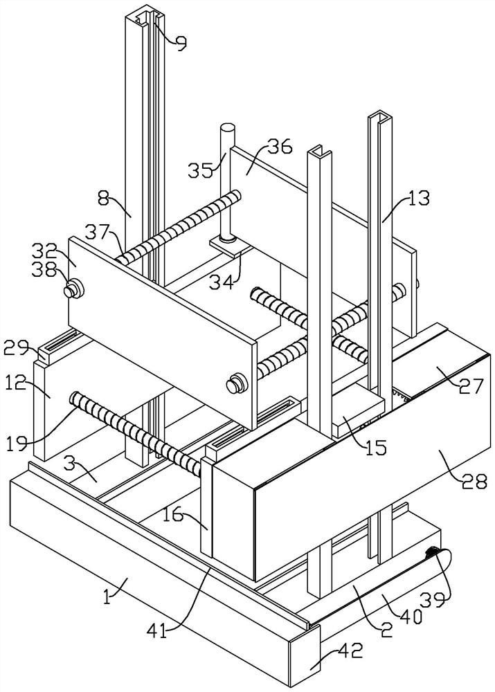
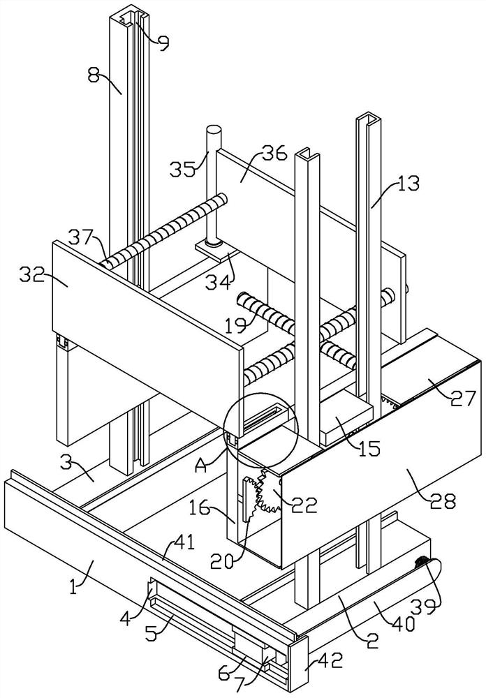
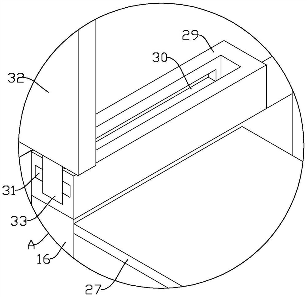
[0027] refer to Figure 1-8, a formwork reinforcement device for construction, comprising a base 1, a front base 2 and a rear base 3, one end of the rear base 3 is fixedly mounted on the base 1, a groove 4 is opened on one side of the base 1, and the upper and lower ends of the groove 4 Both are provided with a first card slot 5, and a first card block 6 is slidably arranged in the first card slot 5, and a block 7 is slidably arranged in the slot 4, and the upper and lower ends of the block 7 are respectively fixedly connected with the first card block 6, and the front One end of the side base 2 is fixedly connected to the block 7, and the top of the rear base 3 is fixedly equipped with a rear side slide rail 8, and both sides of the rear side slide rail 8 are provided with a second card slot 9, and the second card slot 9 is slidingly arranged There is a second block 10, and a first slider 11 is slidably arranged in the rear side slide rail 8, and both sides of the first slide...
Embodiment 2
[0032] Since the working environment of the device is mostly on the construction site, it will inevitably be affected by dust and the mud inside the formwork. A series of transmission structures in Example 1, such as the tooth disc and the surface of the screw rod, when there are mud dust and other pollutants, will be affected. Cause transmission to be blocked, not smooth or even stuck by solidified mud, refer to Figure 1-8 , as another preferred embodiment of the present invention, the difference from Embodiment 1 is that two oppositely arranged U-shaped frames 27 are provided on one side of the front side pressing plate 16, and a gap is provided between the two U-shaped frames 27, and The two front side slide rails 13 are located between the two U-shaped frames 27, the upper end of one side of the U-shaped frame 27 is hinged with a cover plate 28, and the two first toothed discs 20 and the fourth toothed disc 25 are located In the space formed by side pressure plate 16 and ...
PUM
 Abstract
Description
Claims
Application Information
 - R&D Engineer
- R&D Manager
- IP Professional
- Industry Leading Data Capabilities
- Powerful AI technology
- Patent DNA Extraction
Browse by: Latest US Patents, China's latest patents, Technical Efficacy Thesaurus, Application Domain, Technology Topic, Popular Technical Reports.
© 2024 PatSnap. All rights reserved.Legal|Privacy policy|Modern Slavery Act Transparency Statement|Sitemap|About US| Contact US: help@patsnap.com


