
Wirelessly-controlled LED lamp induction circuit

A technology of LED lamps and induction circuits, applied in energy-saving control technology, electrical components, etc., can solve the problem of inconvenient modification of induction parameters, and achieve the effect of small deviation and not easy to trigger by mistake

Pending Publication Date: 2020-09-01
NINGBO OUTLUX ELECTRICAL CO LTD
View PDF0 Cites 0 Cited by
  • Summary
  • Abstract
  • Description
  • Claims
  • Application Information

AI Technical Summary

Problems solved by technology

[0005] The third is that it is very inconvenient to modify the sensing parameters again after the user's LED lights are installed.

Method used


Image

  • Wirelessly-controlled LED lamp induction circuit
  • Wirelessly-controlled LED lamp induction circuit
  • Wirelessly-controlled LED lamp induction circuit

Examples


Embodiment

[0042] The following is attached Figure 1-4 The present invention is described in further detail.

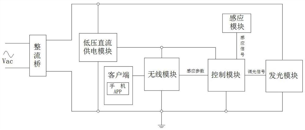
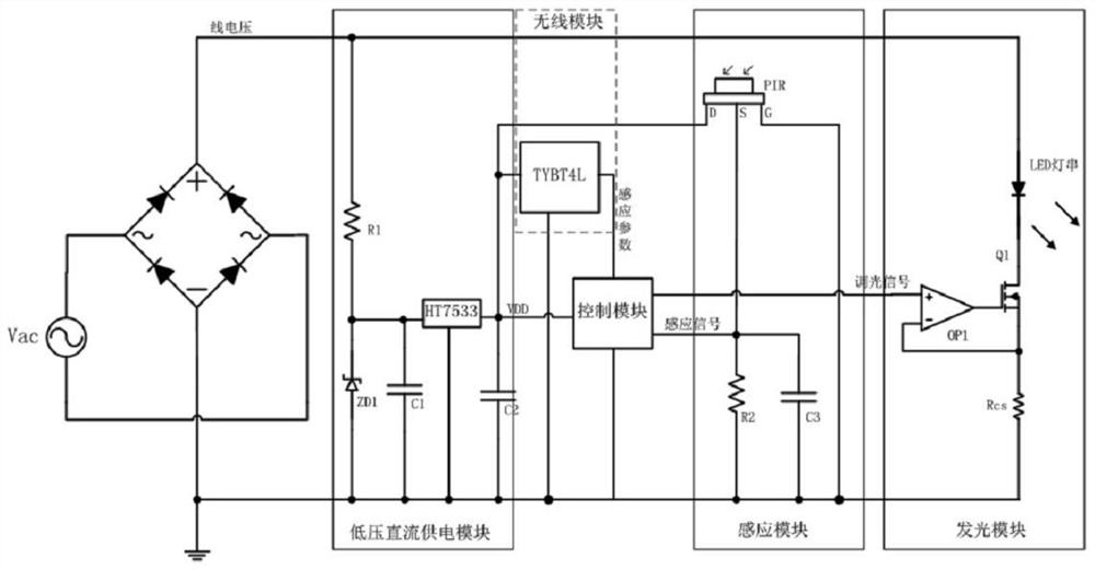
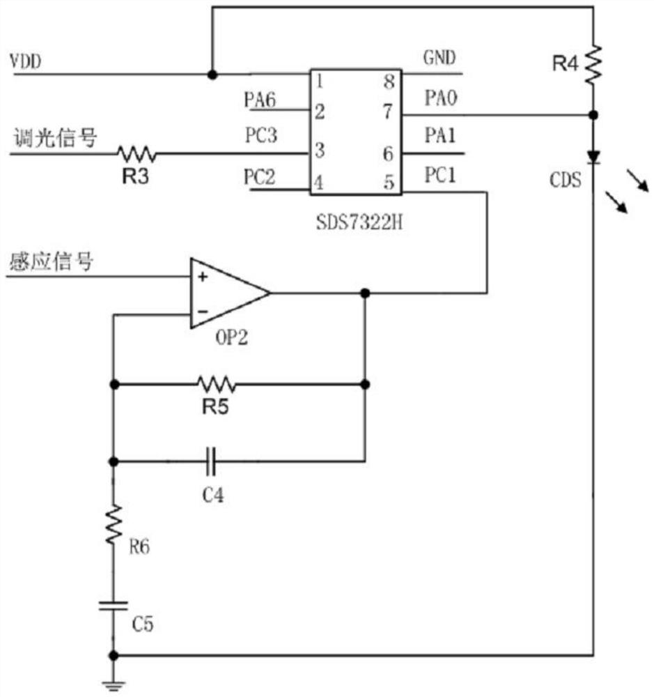
[0043] A wirelessly controlled LED light sensing circuit, such as Figure 1-4 As shown, including rectifier bridge, low voltage DC power supply module, control module, light emitting module, sensing module, wireless module and client;

[0044] The rectifier bridge supplies power to the light-emitting module after rectification;

[0045] The low-voltage DC power supply module supplies power to the wireless module and the control module respectively with the power rectified by the rectifier bridge;

[0046] The control module receives and processes the sensing parameters from the wireless module and the sensing signal from the sensing module, and outputs a dimming signal to the light emitting module after calculation by an algorithm preset in the control module.

[0047] Further, the light emitting module receives a dimming signal from the control module, and the dimming signa...


PUM


Abstract

The invention discloses a wirelessly-controlled LED lamp induction circuit, which comprises a rectifier bridge, a low-voltage DC power supply module, a control module, a light emitting module, an induction module, a wireless module and a client, and the rectifier bridge supplies power to the light emitting module after rectification. According to the wirelessly-controlled LED lamp induction circuit, compared with an adjustable potentiometer mode, each induction parameter can be accurately adjusted in a mobile phone APP or controller mode, an adjustable potentiometer is not used, so that the induction parameters of the LED lamps are small in deviation and not easy to trigger by mistake, what you see is what you get, the induction parameters corresponding to the set values can be known without testing the LED lamps, and after a user installs the LED lamps, the LED lamps are easier to modify again and only need to be operated on a mobile phone APP or a controller. Meanwhile, the infraredinduction LED lamp can be set to be a light-operated lamp, an induction lamp or a common lamp for use through the mobile phone APP or the controller, and the effect that one lamp has multiple purposesis achieved.

Description

technical field [0001] The invention relates to the technical field of LED lamps, more specifically, it relates to a wirelessly controlled LED lamp sensing circuit. Background technique [0002] Traditional LED sensor lamps use adjustable potentiometers to adjust the delay time, sensing sensitivity and illuminance. There are three problems: [0003] One is that when the adjustable potentiometer knob is adjusted to the same position, the resistance value deviation is large, and the error reaches 30%, which leads to a large deviation in the adjustment of the sensing parameters between the LED lights, especially the excessive deviation of the sensing sensitivity, which will lead to false triggering. Lights turn on when they shouldn't, and don't turn on when they should; [0004] The second is that after the adjustable potentiometer knob is adjusted to a certain position and fixed, I don’t know what the corresponding actual sensing parameter value is. It is necessary to test t...

Claims


Application Information

Patent Timeline
IPC IPC(8): H05B45/10H05B47/11H05B47/115H05B47/17H05B47/19
CPCH05B45/10H05B47/11H05B47/115H05B47/17H05B47/19Y02B20/40
Inventor 朱飞彪王红霞马东元
Owner NINGBO OUTLUX ELECTRICAL CO LTD
Learn More