Air-drying equipment for aerated concrete blocks
A technology of aerated concrete and blocks, applied in the field of aerated bricks, can solve the problems of low air-drying efficiency and affecting the preparation effect, and achieve the effects of improving effect and efficiency, ensuring work safety, and facilitating handling
- Summary
- Abstract
- Description
- Claims
- Application Information
AI Technical Summary
Problems solved by technology
Method used
Image
Examples
Embodiment 1
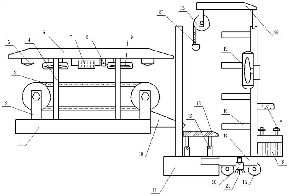
[0020] Example 1: Please refer to Figure 1-3 , an air-drying equipment for air-entrained concrete blocks, comprising a base 1, the base 1 is provided with a conveyor belt bracket 2, and the conveyor belt bracket 2 is provided with a conveyor belt 3, and the mold is removed after the aerated concrete block is prepared Place it on the conveyor belt 3 to facilitate its subsequent air-drying treatment, ensuring safety and convenient use.
[0021] The base 1 is provided with a support column 4, the top of the support column 4 is provided with a ceiling 5, and multiple sets of heat dissipation fans 9 are installed on the lower surface of the ceiling 5. When the aerated concrete block moves on the conveyor belt 3, the multiple sets of heat dissipation fans 9 pairs are turned on. It performs blowing and heat dissipation, evaporates the water therein, facilitates the air-drying of the aerated block, is beneficial to the effect and efficiency of the aerated block preparation, and is co...
Embodiment 2
[0028] Embodiment 2: On the basis of Embodiment 1, a camera 8 is installed on the ceiling 5, and the camera 8 is wirelessly connected to the remote display center. Through the camera 8, the air-drying condition of the aerated concrete block can be clearly checked to ensure the safety of the device. easy to use.
[0029] A plurality of groups of lighting lamps 6 are installed on the ceiling 5, and the lighting lamps 6 are convenient to provide lighting at night or in the dark, which is conducive to the normal operation of the device and is convenient to use.
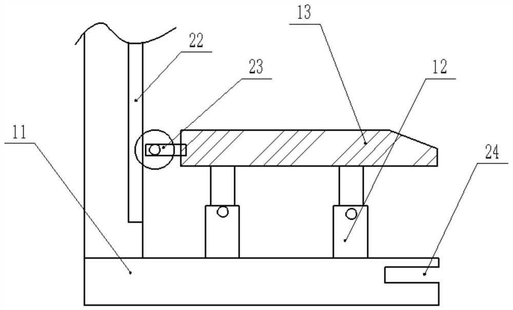
[0030] One end of the top plate 13 is provided with a pulley 23, and the side wall of the fixed frame 11 is provided with a chute 22. The pulley 23 is arranged inside the chute 22, and the top plate 13 is driven by the elevating rod 12 to cooperate with the chute 22 by the pulley 23. It is beneficial to ensure that the top plate 13 moves up and down on the fixed frame 11, ensuring safety and being convenient to use.
[0...
PUM
 Abstract
Description
Claims
Application Information
 - R&D
- Intellectual Property
- Life Sciences
- Materials
- Tech Scout
- Unparalleled Data Quality
- Higher Quality Content
- 60% Fewer Hallucinations
Browse by: Latest US Patents, China's latest patents, Technical Efficacy Thesaurus, Application Domain, Technology Topic, Popular Technical Reports.
© 2025 PatSnap. All rights reserved.Legal|Privacy policy|Modern Slavery Act Transparency Statement|Sitemap|About US| Contact US: help@patsnap.com


