Excavator for mine
A technology for excavators and mines, which is applied in earth movers/shovels, dispersed particle filtration, construction, etc. It can solve problems such as blockage of heat dissipation holes of heat dissipation components, high internal dust content, and influence on heat dissipation efficiency, so as to prevent dust accumulation Excessive, good cleaning effect
- Summary
- Abstract
- Description
- Claims
- Application Information
AI Technical Summary
Problems solved by technology
Method used
Image
Examples
Embodiment 1
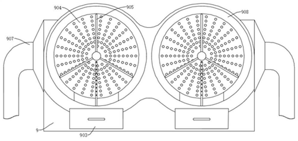
[0029] refer to Figure 1-5 , a mine excavator, comprising an excavator body and an installation box 9 fixedly connected to the excavator body, the installation box 9 is provided with an air inlet 908, and the air inlet 908 is fixedly connected with a filter screen 904, and the filter screen 904 A cleaning shaft 7012 is rotatably connected, and a cleaning rod 905 is fixedly connected to the cleaning shaft 7012. A third rotating shaft 906 is fixedly connected to the bottom of the filter screen 904, and a dust falling rod 9062 matched with the cleaning rod 905 is rotatably connected on the third rotating shaft 906. Rotatingly be connected with box door 902 on the box 9, be fixedly connected with drive motor 7015 on the box door 902, the output end of drive motor 7015 is connected with drive shaft 7011, is circumferentially evenly distributed on the drive shaft 7011 and has suction plate 702, drive shaft 7011 Cooperate with the cleaning shaft 7012, the bottom of the installation ...
Embodiment 2
[0032] refer to Figure 5-7 , and also includes that the working mechanism is composed of a three-section arm and a bucket 1. The three-section arm is composed of a forearm 6, a middle arm 7 and a rear arm 8. The rear arm 8 is rotatably connected to the body of the excavator base, and the middle arm 7 is rotatably connected to the rear arm. 8. The middle arm 7 is rotatable at the end far away from the body of the excavator base. One end of the forearm 6 is rotatably connected to the middle arm 7. The other end of the forearm 6 is rotatably connected to the mounting seat 5. The bucket 1 can swing on the mounting seat 5. It can be rotated, and a cleaning mechanism is arranged in the bucket 1 .
[0033] A fifth oil cylinder 802 is rotatably connected to the body of the excavator base, the output end of the fifth oil cylinder 802 is rotatably connected to the rear arm 8, and the fourth oil cylinder 801 is rotatably connected to the rear arm 8, and the output end of the fourth oil ...
Embodiment 3
[0039] refer to Figure 6 and Figure 8 , is basically the same as Embodiment 2, furthermore, the cleaning mechanism includes a second oil cylinder 303 and a first rotating shaft 105, and the bucket 1 is evenly distributed with second through holes 101 on the circumference, and the first rotating shaft 105 is rotatably connected to the second through hole. In the hole 101, the second oil cylinder 303 is fixedly connected to the side wall of the swing seat 3, the output end of the second oil cylinder 303 is fixedly connected to the gear ring 3031, and the two ends of the first rotating shaft 105 are respectively connected to the third gear 1051 and the blade 1052, The third gear 1051 meshes with the gear ring 3031; the outer wall of the bucket 1 is fixedly connected with a protective ring 103, and the third gear 1051 is rotatably connected in the protective ring 103; The protective cover 102 and the blades 1052 are rotatably connected in the protective cover 102; the number of...
PUM
 Abstract
Description
Claims
Application Information
 - R&D Engineer
- R&D Manager
- IP Professional
- Industry Leading Data Capabilities
- Powerful AI technology
- Patent DNA Extraction
Browse by: Latest US Patents, China's latest patents, Technical Efficacy Thesaurus, Application Domain, Technology Topic, Popular Technical Reports.
© 2024 PatSnap. All rights reserved.Legal|Privacy policy|Modern Slavery Act Transparency Statement|Sitemap|About US| Contact US: help@patsnap.com


