Device for batched cutting of empty ring-pull cans
A cans and batch technology, which is applied to shearing devices, accessories of shearing machines, feeding devices, etc. to improve the cutting efficiency and prevent hands from being cut.
- Summary
- Abstract
- Description
- Claims
- Application Information
AI Technical Summary
Problems solved by technology
Method used
Image

Examples
Embodiment 1
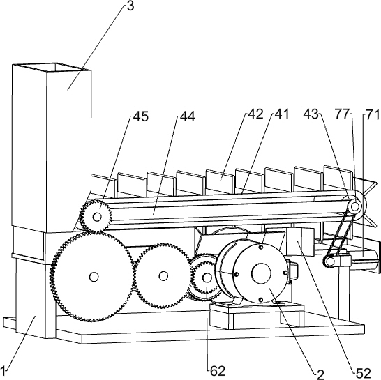
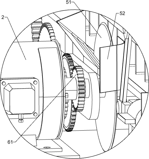
[0024] A device for cutting empty pop cans in batches, such as Figure 1-6 As shown, it includes a base 1, a servo motor 2, a storage tank 3, a first transmission mechanism 4, a first cutting mechanism 5, and a reduction mechanism 6. The servo motor 2 is installed on the left side of the top of the base 1, and the top rear side of the base 1 The storage tank box 3 is connected, the first transmission mechanism 4 is installed on the outer surface of the storage tank box 3, and the speed reduction mechanism 6 is installed on the base 1 on the rear side of the servo motor 2, and the speed reduction mechanism 6 includes a main power gear 61 and a speed reduction gear Group 62, a reduction gear set 62 is installed on the base 1 on the rear side of the servo motor 2, the output shaft of the servo motor 2 is connected with the main power gear 61 through a coupling, and the main power gear 61 is connected to the first transmission mechanism through the reduction gear set 62 4 transmis...
Embodiment 2
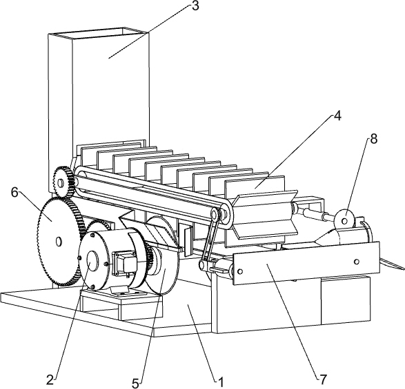
[0029] On the basis of Example 1, such as Figure 1-4 and Figure 7 As shown, the second transmission mechanism 7 is also included, and the second transmission mechanism 7 includes a second transmission belt 71, a limit baffle plate 72, a push plate 73, a transmission shaft 74, a first power transmission gear 75, a second power transmission gear 76 and power transmission belt group 77, the front side upper part of base 1 is connected with limit baffle plate 72, and the left and right sides of limit baffle plate 72 inner surfaces are all rotatably connected with drive shaft 74, pass belt between two drive shafts 74 A second conveyor belt 71 is connected inside, a plurality of push plates 73 are evenly spaced on the second conveyor belt 71, the rear end of the left transmission shaft 74 passes through the front side of the base 1, and the rear end of the left transmission shaft 74 is connected with The first power transmission gear 75, the inner surface of the base 1 on the lef...
Embodiment 3
[0032] On the basis of Example 2, such as figure 1 , figure 2 , Figure 4 , Figure 5 and Figure 7As shown, the second cutting mechanism 8 is also included, and the second cutting mechanism 8 includes a second cutting wheel 81, a bevel gear connecting rod 82, a limit frame 83, a transmission bevel gear 84, a transmission belt 85, a pulley 86, a conical Block 87 and wedge-shaped block 88, the right side front side of right side fixed mount 44 is connected with limit frame 83, and the bottom rotation type of limit frame 83 is connected with bevel gear connecting rod 82, and the right side middle part of right side fixed mount 44 rotates The transmission bevel gear 84 is connected with the transmission bevel gear 84, and the transmission bevel gear 84 meshes with the bevel gear connecting rod 82. The transmission shaft of the transmission bevel gear 84 and the right end of the power shaft 53 are connected with a pulley 86, and a transmission belt 85 is connected between the ...
PUM
 Abstract
Description
Claims
Application Information
 - R&D
- Intellectual Property
- Life Sciences
- Materials
- Tech Scout
- Unparalleled Data Quality
- Higher Quality Content
- 60% Fewer Hallucinations
Browse by: Latest US Patents, China's latest patents, Technical Efficacy Thesaurus, Application Domain, Technology Topic, Popular Technical Reports.
© 2025 PatSnap. All rights reserved.Legal|Privacy policy|Modern Slavery Act Transparency Statement|Sitemap|About US| Contact US: help@patsnap.com