Heart valvuloplasty traction system

A heart valve and traction mechanism technology, applied in the field of medical devices, can solve the problems of large size of the telescopic rod, complex adjustment movement, poor flexibility, etc., to increase the overall hardness and limit ability, reduce visual field occlusion, and compact movable beads. Effect

Pending Publication Date: 2020-09-01
程兆云
View PDF0 Cites 0 Cited by
  • Summary
  • Abstract
  • Description
  • Claims
  • Application Information

AI Technical Summary

Problems solved by technology

[0003] Another set of pulling device is actually a bracket installed on the sternum spreader, and is equipped with telescopic rods and pulling claws. The actual position of the pulling claws is changed by the telescopic effect of the telescopic rods, and the pulling claws directly pull the human tissue. Affected by the structure of the telescopic rod, the size of the telescopic rod is relatively large, especially when multiple human tissues need to be pulled at the same time, multiple telescopic rods are required, which seriously affects the field of vision and limits the doctor's surgical actions. When operating with a knife, you will be concerned about whether your hand will touch the telescopic rod. The more you use the telescopic rod, the greater the probability of touching it. Moreover, the telescopic rod is a relatively rigid part and has poor flexibility. In actual operation, If it is necessary to adjust the pulling torque or pulling angle of the claw, it is also necessary to change the installation position and telescopic length of the telescopic rod to perform more complicated adjustment movements

Method used


Image

  • Heart valvuloplasty traction system
  • Heart valvuloplasty traction system
  • Heart valvuloplasty traction system

Examples


Embodiment Construction

[0026] The following will clearly and completely describe the technical solutions in the embodiments of the present invention with reference to the accompanying drawings in the embodiments of the present invention. Obviously, the described embodiments are only some, not all, embodiments of the present invention. Based on the embodiments of the present invention, all other embodiments obtained by persons of ordinary skill in the art without making creative efforts belong to the protection scope of the present invention.

[0027] In the description of the present invention, it should be noted that the terms "upper", "lower", "inner", "outer", "front end", "rear end", "both ends", "one end", "another end" The orientation or positional relationship indicated by etc. is based on the orientation or positional relationship shown in the drawings, and is only for the convenience of describing the present invention and simplifying the description, rather than indicating or implying that ...


PUM


Abstract

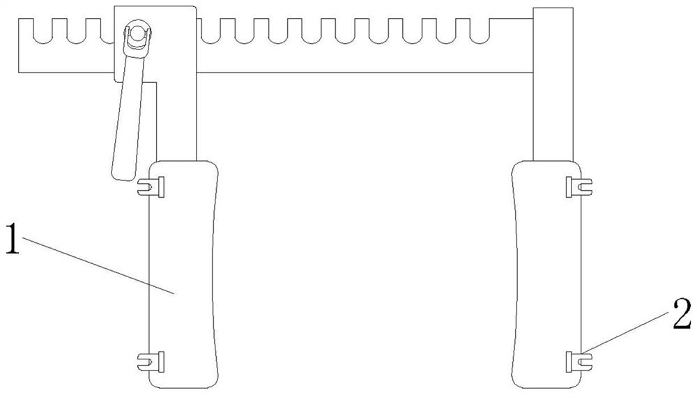
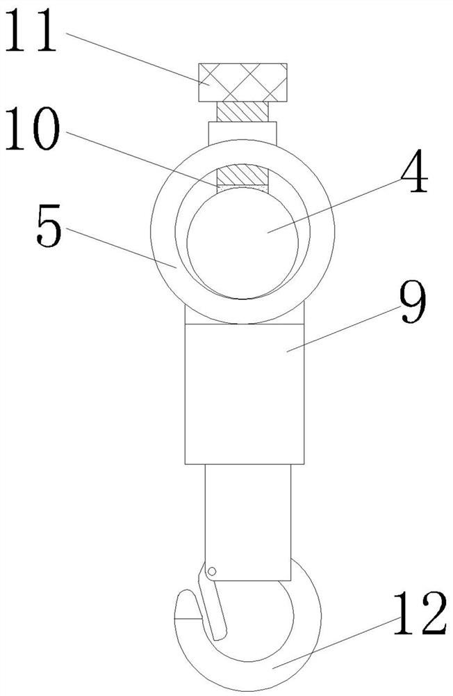
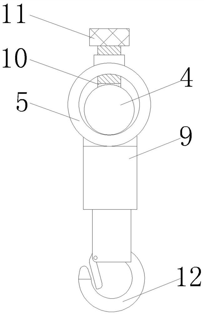
The invention discloses a heart valvuloplasty traction system. The system comprises a spreader body, wherein a supporting frame is detachably mounted on the spreader body; a second adjusting table isdetachably mounted on the supporting frame; a clamping cylinder is mounted on the second adjusting table; a fine adjustment mechanism is movably mounted on the clamping cylinder; a pull rope is installed on the fine adjustment mechanism, a movable ball is installed on the pull rope, the two ends of the pull rope extend outwards through the two ends of the clamping cylinder, a pull claw is installed at one end of the pull rope, a first adjustment table is detachably installed on the portion, on one side of the first adjustment table, of the supporting frame, and a traction mechanism playing atraction role on the pull rope is installed on the first adjustment table. According to the heart valvuloplasty traction system, a series of structures are arranged, so that the heart valvuloplasty traction system takes the sternum dilator as a basis during a valvuloplasty operation, interference on a doctor operation is avoided by virtue of the small-size characteristic of the rope body, the traction of the rope body is adjusted, and the operation use requirements are met.

Description

technical field [0001] The invention relates to the technical field of medical devices, in particular to a pulling system for heart valve forming. Background technique [0002] During the sternal distraction operation, it is necessary to use the sternal distractor to distract the sternum and at the same time cover the incision tissue to avoid affecting the doctor's field of vision during the operation. In actual operations, such as valvuloplasty, In addition to the sternum distraction, it is also necessary to remove the tissue around the heart to avoid covering the actual surgical site, and the removed human tissue needs to be stretched by other parts to avoid tissue reset and cover the surgical site. During this process, In addition to the sternal distractor, another set of stretching devices is required for use. [0003] Another set of pulling device is actually a bracket installed on the sternum spreader, and is equipped with telescopic rods and pulling claws. The actual...

Claims


Application Information

Patent Timeline
Patent Type & Authority Applications(China)
IPC IPC(8): A61B17/02
CPCA61B17/0206
Inventor 程兆云胡俊龙王燕平孟树萍刘超葛振伟王圣孙俊杰轩继中王保才赵子牛赵健刘前进
Owner 程兆云
Why Eureka
Try Eureka