A kind of capacitor production equipment and process

A technology for producing equipment and capacitors, applied in the direction of capacitors, capacitor manufacturing, winding capacitor machines, etc., can solve problems such as affecting the quality of capacitors, producing bubbles in dye liquor, and no air removal.

Active Publication Date: 2022-04-05
NINGBO BAOCHENG ELECTRIC CO LTD
View PDF7 Cites 0 Cited by
  • Summary
  • Abstract
  • Description
  • Claims
  • Application Information

AI Technical Summary

Problems solved by technology

[0004] The above-mentioned prior art solution has the following defects: the above-mentioned process does not remove the air in the impregnating agent delivery pipeline during impregnation, and the dyeing solution generates air bubbles during the impregnating agent transportation, which affects the quality of the produced capacitor

Method used


Image

  • A kind of capacitor production equipment and process
  • A kind of capacitor production equipment and process
  • A kind of capacitor production equipment and process

Examples


Embodiment 1

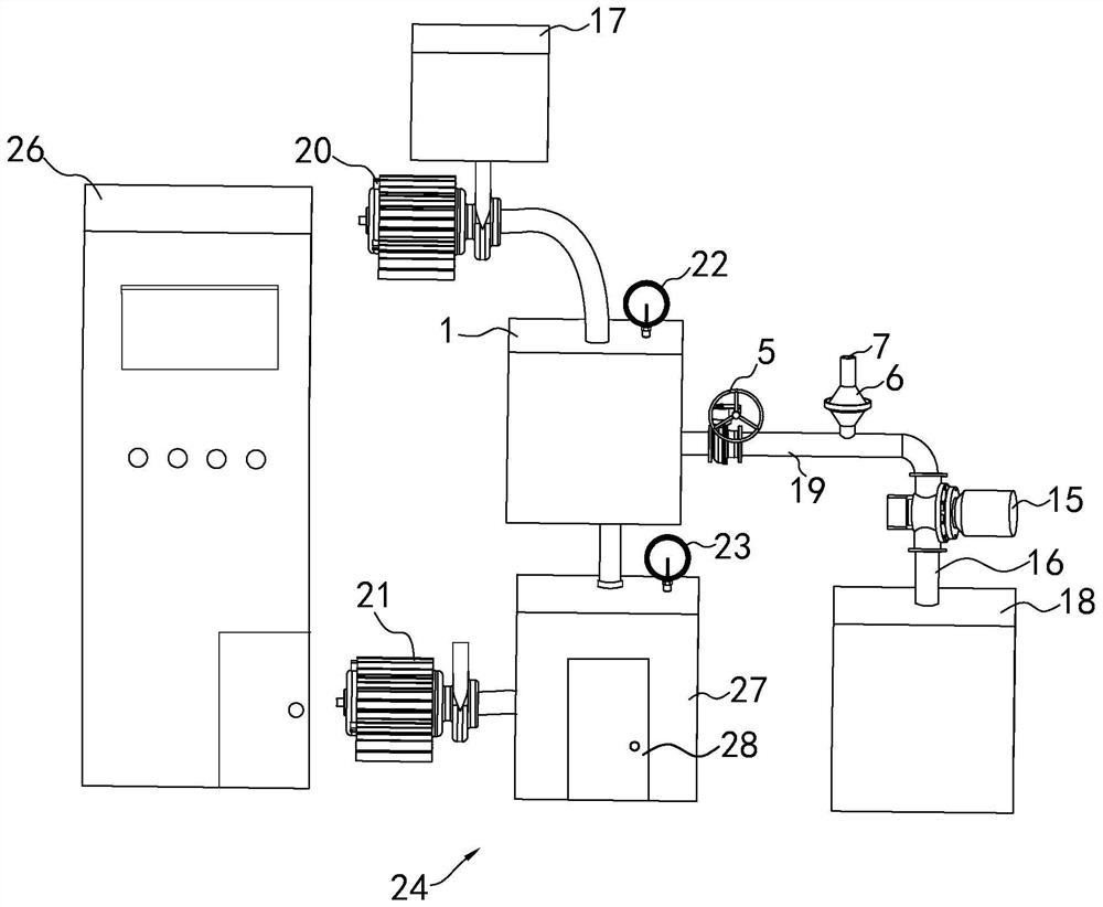
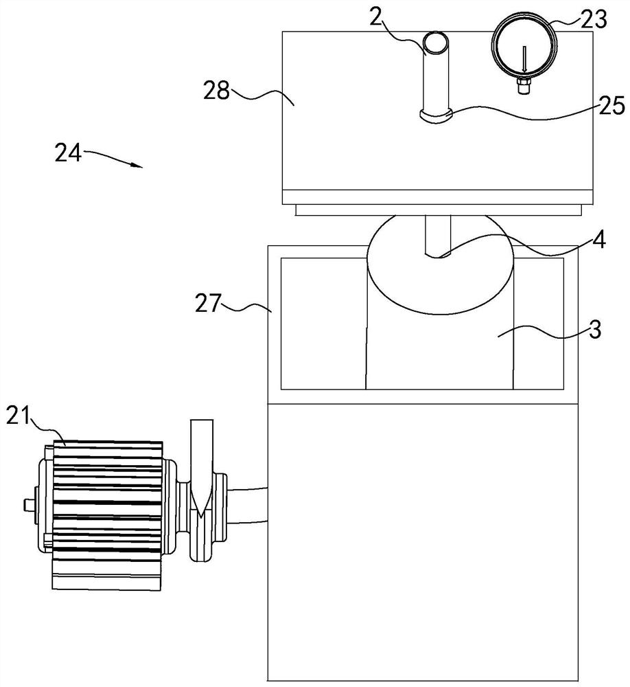
[0050] refer to figure 1 and figure 2 , is a capacitor production equipment disclosed in the present invention, comprising a vacuum tank 1, the upper end of the vacuum tank 1 is connected with a first vacuum pump 20, the lower end of the vacuum tank 1 is connected with an oil injection pipe 2, and the end of the oil injection pipe 2 is connected with a vacuum protection box 24 , the vacuum protection box 24 includes a box body 27 , the box body 27 is detachably connected with a placement door 28 , and the oil filling pipe 2 is inserted into the box body 27 through the upper end of the box body 27 . The oil filling pipe 2 and the box body 27 are detachably connected to facilitate the replacement of the vacuum protection box 24. A sealing ring 25 is provided at the connection between the box body 27 and the oil filling pipe 2. The sealing ring 25 seals the connection between the oil filling pipe 2 and the box body 27. The airtightness of the vacuum protection box 24 is ensured...

Embodiment 2

[0058] refer to figure 2 , a capacitor production process, which includes the following steps:

[0059] S1. Die cutting: the zinc-aluminum alloy is thinned and cut into metal sheets suitable for the production of capacitors 3;

[0060] S2, winding: the electrolytic paper is placed on the metal sheet after adsorbing the electrolyte, and the electrolytic paper and the metal sheet are wound layer by layer to form a cylinder;

[0061] S3. Gold spray: spray gold on both sides of the cylinder formed by winding the electrolytic paper and the metal sheet to facilitate welding;

[0062] S4. Welding: Weld the positive lead of the capacitor and the negative lead of the capacitor to the two sides of the electrolytic paper and the metal sheet respectively;

[0063] S5. Assembly: place the cylinder formed by the electrolytic paper and the metal sheet in the aluminum shell with the impregnation port 4;

[0064] S6, vacuum oil injection:

[0065] a. Heat the insulating oil to 70℃-80℃ for...


PUM


Abstract

The invention discloses a capacitor production equipment and process, which is applied in the field of capacitor production, and solves the problem that the air in the impregnating agent delivery pipeline is not removed when the capacitor is impregnated, and the dye solution produces air bubbles during the impregnating agent transportation process. A technical problem that affects the quality of produced capacitors. The main point of the technical solution is a capacitor production equipment, including a vacuum tank. Buffer tube, there is a pipeline valve at the connection between the buffer tube and the vacuum tank, and the outer wall of the upper end of the buffer tube is connected with a vent pipe, and the upper end of the vent pipe is provided with a vent port, and the diameter of the cross section of the vent pipe increases first and then becomes smaller from bottom to top , the air release pipe is provided with a floating block, the outer wall of the floating block is attached to the inner wall of the lower end of the air release pipe; the technical effect is to ensure the vacuum state in the capacitor and ensure the quality of the produced capacitor.

Description

technical field [0001] The invention relates to the technical field of capacitor production, in particular to a capacitor production equipment and process. Background technique [0002] With the rapid development of the electronic industry, the demand for capacitors is increasing, and the requirements for the quality of capacitors are also getting higher and higher. In the production process of capacitors, vacuum drying and impregnation is the most important and critical process. During the impregnation process, the capacitor needs to be evacuated, and then the impregnating agent is injected through the impregnation port of the capacitor. If the capacitor contains air or steam in the process of dipping, it is easy to generate bubbles in the impregnating agent, which affects the effect of dipping. [0003] The Chinese patent with the existing publication number CN107452509A discloses a production process of an aluminum electrolytic capacitor, including the following contents...

Claims


Application Information

Patent Timeline
Patent Type & Authority Patents(China)
IPC IPC(8): H01G13/00H01G13/02H01G13/04
CPCH01G13/00H01G13/003H01G13/04H01G13/02H01G13/006
Inventor 陈平
Owner NINGBO BAOCHENG ELECTRIC CO LTD
Why Eureka
Try Eureka